


35
4
3
5
2
8
6
7
1
10
11
9
12
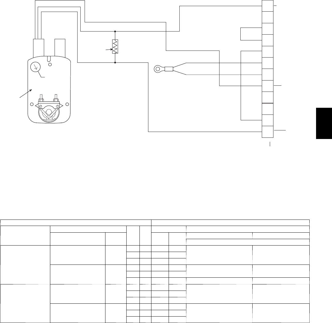
PINK
VIOLET
BLACK
BLUE
YELLOW
NOTE 1
NOTE 3
RUN
500 OHM
RESISTOR
50HJ540573
ACTUATOR
ASSEMBLY
RED
WHITE
ECONOMISER2 PLUG
DIRECT DRIVE
ACTUATOR
4-20mA SIGNAL
OAT SENSOR
4-20 mA
position
input signal
24 VAC
TRANSFORMER
GROUND
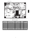
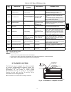
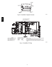
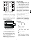
NOTES:
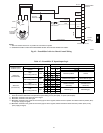
1. Switch on actuator must be in run position for economizer to operate.
2. 50HJ540573 actuator consists of the 50HJ540567 actuator and a harness with 500-ohm resistor.
C08436
Fig. 42 -- EconoMi$er2 with 4 to 20 mA Control Wiring
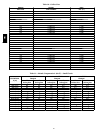
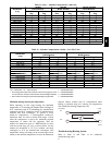
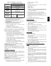
Table 15 – EconoMi$er IV Input/Output Logic
INPUTS OUTPUTS
Demand Control
Ventilation (DCV)
Enthalpy*
Y1 Y2
Compressor NTerminal†
Outdoor Return
Stage
1
Stage
2
Occupied Un occupied
Damper
Below set
(DCV LED O ff)
High
(F ree Cooling LED Off)
Low
On On On On
Minimum position ClosedOn Off On Off
Off Off Off Off
Low
(F ree Cooling LED On)
High
On On On Off
Modulating** (between min.
position and full - open)
Modulating** (between
closed and full-open)
On Off Off Off
Off Off Off Off Minimum position Closed
Above set
(DCV LED On)
High
(F ree Cooling LED Off)
Low
On On On On
Modulating†† (between min.
position and DCV
maximum)
Modulating†† (between
closed and DCV
maximum)
On Off On Off
Off Off Off Off
Low
(F ree Cooling LED On)
High
On On On Off
Modulating*** Modulating†††On Off Off Off
Off Off Off Off
* For single enthalpy control, the module compares outdoor enthalpy to the ABCD s etpoint.
† Power at N terminal determines Occupied/Unoccupied setting: 24 vac (Occupied), no power (Unoccupied).
** Modulation is based on the supply-air sensor signal.
†† Modulation is based on the DCV signal.
*** Modulation is based on the greater of DCV and supply-air sensor signals, between minimum position and either maximum position (DCV)
or fully open (supply-air signal).
††† Modulation is based on the greater of DCV and supply-air sensor signals, between closed and either maximum position (DCV) or fully
open (supply-air signal).
580J