


22
NOTE: All troubles are latched by t he duct smoke
detector. The trouble c ondition must be c leared and then
the duct smoke detector must be reset in order to restore it
to the normal state.
Resetting Alarm a nd Tr ouble Condition T
rips:
Manual reset is required to restore smoke detector systems
to Normal operation. For installations using two sensors,
the duct smoke detector does not differentiate which
sensor signals an alarm or trouble condition. Check each
sensor for Alarm or Trouble sta tus (indicated by LED).
Clear the condition that has generated the trip at this
sensor. Then reset the sensor by pressing and holding the
reset button (on the side) for 2 seconds. Verify that the
sensor’s Alarm and Trouble LEDs are now off. At the
controller, clear its Alarm or Trouble state by pressing and
holding the manual reset butt on (on the front cover) for 2
seconds. Verify that the controller’s Alarm and Trouble
LEDs are now off. Replace all panels.
Troubleshooting
Controller’ s Tr ouble LED is On
1. Check the Trouble LED on each sensor connected to
the controller. If a sensor’s Trouble LED is on, de -
termine the cause and make the necessary repairs.
2. Check the wiring between the sensor and the control-
ler. If wiring is l oose or missing, repair or replace a s
required.
Controller’ s Tr ouble LED is
Flashing
1. One or both of the sensors is 100% dirty.
2. Determine which Dirty LED is flashing then clean
that sensor assembly as described in the detector
cleaning section.
Sensor’s Tr ouble LED is
On
1. Check the sensor’s Dirty LED. If it is flashing, the
sensor is dirty and must be cleaned.
2. Check the sensor’s cover. If it is loose or missing, se-
cure the c over to the sensor housing.
3. Replace sensor assembly.
Sensor’s Power LED is
Off
1. Check the controller’s Power L ED. If it is off, de-
termine why the controller does not have power and
make the necessary repairs.
2. Check the wiring between the sensor and the control-
ler. If wiring is l oose or missing, repair or replace a s
required.
Controller’s Power LED is
Off
1. Make sure the cir cuit supplying power to the control-
ler is opera tional. If not, make sure JP2 and JP3 are
set correctly on the controller before applying power.
2. Verify t hat power is applied to the controller’s supply
input terminals. If power is not pre sent, replace or re-
pair wiring as required.
Remote Test/Reset Station’s Trouble LED Does
Not
flash When Performing a Dirty Test, But
the
Controller’ s Tr ouble LED
Does
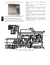
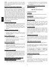
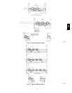
1. Verify that the remote test/station is wired as shown
in Fig. 23. Repair or replace loose or missing wiring.
2. Configure the sensor dirty test to activate the cont rol-
ler’s supervision relay. See “Changing sensor dirty
test operation.”
Sensor’s Tr ouble LED is On, But t he Controller’
s
Trouble LED is
OFF
Remove JP1 on the controller.
PROTECTIVE DEVICES
Compressor Protection
Overcurrent
The compressor has internal linebreak motor protection.
Overtemperatur
e
The com pressor has an internal protector to protect it
agai nst excessively high discharge gas temperatures.
High Pressure
Switch
The system is provided with a high pressure switch
mounted on the discharge line. The switch is
stem--mounted and brazed into the discharge tube. Trip
setting is 630 psig +/-- 10 psig (4344 +/-- 69 kPa) when
hot. Reset is automatic at 505 psig (3482 kPa).
Low Pressure
Switch
The system is protected against a loss of charge and low
evaporator coil loading condition by a low pressure switch
located on the suction line near the compressor. The
switch is stem--mounted. Trip setting is 54 psig +/-- 5 psig
(372 +/ -- 34 kPa). Reset is automatic at 117 +/-- 5 psig
(807 +/-- 34 kPa).
Evaporator Freeze Pr
otection
The system is protected against evaporator coil frosting
and low temperature conditions by a tem perature switch
mounted on the evaporator coil hairpin. Trip setting is
30_F+/--5_F(--1_C+/--3_C). Reset is automatic at 45_F
(7_C).
Supply (Indoor) Fan Motor Pr
otection
Disconnect a nd lockout power when servicing fan motor.
The standard supply fan motor is equipped with internal
overcurre nt and overtemperature protec tion. Protection
devices reset automatically.
The High Static option supply fan motor is equipped with
a pilot-- circuit Thermix combination
overtemperature/ overcurrent protec tion device. This
devic e resets automatically. Do not bypass this switch to
correc t trouble. Determine the cause and correct it.
Condenser Fan Motor Pr
otection
The condenser fan motor is internally protected against
overtemperature.
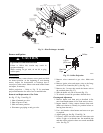
Relief Device
A soft solder joint at the suction service access port
provides pressure relief under abnormal temperature and
pressure conditions (i.e., fire in building). Protect this
joint during brazing operations near this joint.
580J