


23
Control Circuit, 24-- V
The control circui t is protec ted aga inst overcurrent
conditions by a circuit brea ker mounted on control
transformer TRAN. Reset is manual.
GAS HEATING SYSTEM
580J unit heating systems are referenced here according to
unit Gas Heat Option (defined in the unit model number
Position#8) and Heat Level (input capacity, defined in
Positions #9--10--11). See Appendix 1 for a complete unit
model number nomenclature chart.
POSITION # 8 GAS HEAT OPTION
A Nat. Gas / Standard HX and Heat
B Nat. Gas / SS HX and Low NO
x
Heat
C N at. Gas / SS HX and Standard Heat
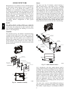
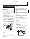
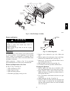
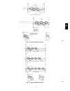
General
The heat exchanger system consists of a gas valve feeding
multiple inshot burners off a manifold. The burners fire
into matching primary tubes. The primary tubes discharge
into combustion plenum where gas flow converges into
secondary tubes. The secondary tubes exit into the
induced draft fan wheel inlet. The induced fan wheel
discharges into a flue passage and flue gases exit out a
flue hood on the side of the unit. The induced draft fan
motor includes a Hall Effect sensor circuit that confirms
adequate wheel speed via the Integrated Gas Control
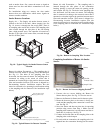
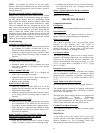
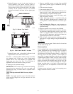
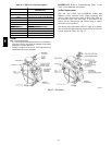
(IGC) board. Safety switches include a Rollout Switch (at
the top of the burner compartment) and a limit switch
(mounted through the fan deck, over the tubes). (See Fig.
27 and Fig. 28.)
INDUCED-
DRAFT
MOTOR
MOUNTING
PLATE
INDUCED-
DRAFT
MOTOR
MANIFOLD
PRESSURE
TAP
VESTIBULE
PLATE
FLUE
EXHAUST
ROLLOUT
SWITCH
BLOWER
HOUSING
GAS
VALVE
BURNER
SECTION
C06152
Fig. 27 -- Burner Section Details
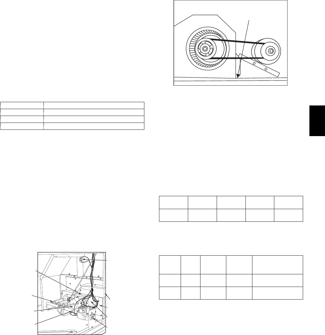
Limit Switch
and Shield
C08284
Fig. 28 -- Limit Switch Location
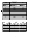
Fuel Types and Pressures
Natural Gas — The 580J unit is factory--equipped for use
with Natural Gas fuel at elevation under 2000 ft (610 m).
See section Orifice Replacement for information in
modifying this unit for installation at elevations above
2000 ft (610 m).
Gas line pressure entering the unit’s main gas valve must
be within specified ranges. Adjust unit gas regul ator valve
as required or consult local gas utility.
Table 4 – Natural Gas Supply Line Pressure Ranges
580J SIZE
GAS
HEAT OPT
HEAT
LEVEL
MIN MAX
All All All
4.0 in. wg
(996 Pa)
13.0 in. wg
(3240 Pa)
Manifold pressure is factory--adjusted for NG fuel use.
Adjust as required to obtain best flame characteristic.
Table 5 – Natural Gas Manifold Pressure Ranges
GAS
HEAT
OPT
HEAT
LEVEL
HIGH
FIRE
LOW
FIRE
RANGE
A, C All
3.5 in. wg
(872 Pa)
1.7 in. wg
(423 Pa){
2.0---5.0 in. wg (Hi)
(498---1245 Pa)
B All
3.5 in. wg
(872 Pa)
NA
2.0---5.0 in. wg (Hi)
(498---1245 Pa)
NA: Not Available
{ 3 Phase models only
Liquid Propane — Accessory packages are available for
field--install ation that will convert the 580J unit (except
low NO
x
model) to operate with Liquid Propane (LP)
fuels. These kits include new orifice spuds, new springs
for gas valves and a supply line low pre ssure switch. See
section on Orifice Replacement for details on orifice size
selec tions.
Low NO
x
models include specially--sized orifices and use
of different flue flow limits and tube baffles. Because of
these extra features, conversion of these models to LP is
not recommended.
Fuel line pressure entering unit gas valve must remain
within specified range.
580J