


24
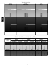
Table 6 – Liquid Propane Supply Line Pressure Ranges
580J SIZE
GAS
HEAT OPT
HEAT
LEVEL
MIN MAX
All A, C All
11.0 in. wg
(2740 Pa)
13.0 in. wg
(3240 Pa)
All B All NA NA
Manifold pressure for LP fuel use must be adjusted to
specified range. Follow instructions in the accessory kit to
make initial readjustment.
Table 7 – Liquid Propane Manifold Pressure Ranges
GAS HEAT
OPT
HEAT LEVEL HIGH FIRE LOW FIRE
A, C All
10.0 in. wg
(2490 Pa)
5.0 in. wg
(1245 Pa){
B All NA NA
NA: Not Available
{ 3 Phase models only
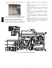
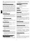
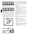
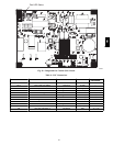
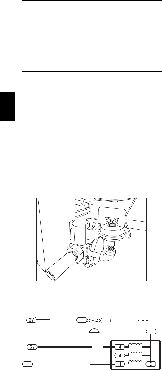
Supply Pressure Switch — The LP c onversion kit includes
a supply low pressure switch. The switch contac ts (from
terminal C to terminal NO) will open the gas valve power
whenever the supply line pressure drops below the
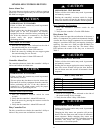
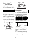
setpoint. See Fig. 29 and Fig. 30. If the low pressure
rema ins open for 15 minutes during a call for heat, the
IGC circuit will initiate a Ignition Fault (5 flashes)
lockout. Reset of the low pressure switch is automatic on
rise in supply line pressure. Reset of the IGC requires a
recycle of unit power after the low pressure switch has
closed.
C08238
Fig. 29 -- L P Low Pressure Switch (Installed)
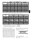
PNK
W2
TSTAT
GRA
BRN
IGC
J2-12
IGC
J2-11
BRN
C
NO
MGV
C
LP LPS
C08285
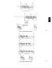
Fig. 30 -- L P Supply Line Low Pressure Switch W iring
This switch also prevents operation when the propane tank
level is low which can result in gas with a high
concentration of impurities, additives, and residues that
have settled to the bottom of the tank. Operation under
these conditions can cause harm to the heat exchanger
system. Contact your fuel supplier if this c ondition is
suspected.
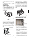
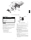
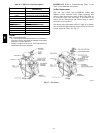
Flue Gas Passageways
To inspect the flue collector box and upper areas of the
heat exchanger:
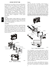
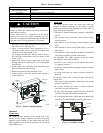
1. Remove the combustion blower wheel and motor as-
sembly according to directions in Combustion-- Air
Blower section. See Fig. 31.
2. Remove the flue cover to inspect the heat exchanger.
3. Clean all surfaces as required using a wire brush.
Combustion--Air Blower
Clean periodi cally to assure proper airflow and heating
efficiency. Inspect blower wheel every fall and
periodically during heating season. For the first heating
season, inspect blower wheel bi--monthly to determine
proper cle aning frequency.
To access burner section, slide the sliding burner partition
out of the unit.
To inspect blower wheel, shine a flashlight into draft hood
opening. If cleaning is required, remove motor and wheel
as follows:
1. Slide burner access panel out.
2. Remove the 7 screws that attach induced--draft motor
housing to vestibule plate. (See Fig. 31.)
3. The blower wheel can be cleaned at this point. If ad-
ditional cleaning is required, continue with Steps 4
and 5.
4. To remove blower from the m otor shaft, remove 2
setscrews.
5. To remove motor, remove the 4 screws that hold the
motor to mounting plate. Remove the motor cooling
fan by removing one setscrew. Then remove nuts that
hold motor to mounting plate.
6. To reinstall, reverse the procedure outlined above.
580J