


33
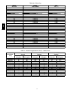
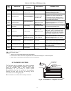
Table 14 – IGC Board LED Alarm Codes
LED
FLASH
CODE
DESCRIPTION
ACTION TAKEN BY
CONTROL
RESET METHOD PROBABLE CAUSE
On Normal Operation — — —
Off Hardware Failure No gas heating. —
Loss of power to the IGC. Check 5 amp fuse
on IGC, power to unit, 24V circuit b reaker,
transformer, and wiring to the IGC.
2Flashes Limit Switch Fault
Gas valve and igniter Off.
Indoor fan and inducer
On.
Limit switch closed, or
heat call (W) Off.
High temperature limit switch is open. Check
the operation of the i ndoor (evaporator) fan
motor.
Ensure that the supply-air temperature rise is
within the range on the unit nameplate. Check
wiring and limit switch operation.
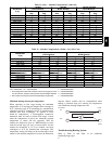
3Flashes Flame Sense Fault
Indoor fan and inducer
On.
Flame sense normal.
Power reset for LED
reset.
The IGC sensed a flame when the gas valve
should be closed. Check wiring, flame sensor,
and gas valve operation.
4Flashes
Four C onsecutive Limit
Switch Fault
No gas heating.
Heat call (W) Off.
Power reset for LED
reset.
4 consecutive limit switch faults within a single
call for heat. See Limit Switch Fault.
5Flashes Ignition Fault No gas heating.
Heat call (W) Off.
Power reset for LED
reset.
Unit unsuccessfully attempted ignition for 15
minutes. Check igniter and flame sensor elec-
trode s pacing, gaps, etc. Check flame sense
and igniter wiring. Check gas valve operation
and gas supply. Ch eck gas valve connections
to IGC terminals. BRN lead must be on Pin 11.
6Flashes Induced Draft Motor Fault
If heat off: no gas
heating.
If heat on: gas valve Off
and inducer O n.
Inducer sense normal,
or heat call (W) Off.
Inducer sense On when heat call Off, or induc-
er sense Off when heat call O n. Check wiring,
voltage, and operation of IGC motor. Check
speed sensor wiring to IGC.
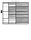
7Flashes Rollout Switch Lockout
Gas valve and igniter Off.
Indoor fan and inducer
On.
Power reset.
Rollout switch has opened. Check gas valve
operation. Check induced-draft blower wheel is
properly secured to motor shaft.
8Flashes Internal Control Lockout No gas heating. Power reset.
IGC has sensed internal hardware or software
error. If fault is not cleared by resetti ng 24 v
power, replace the IGC.
9Flashes
Temporary Software
Lockout
No gas heating.
1 hour auto reset, or
power reset.
Electrical interference is disrupting the IGC
software.
LEGEND
IGC --- Integrated Gas Unit Control
LED --- L ight --- Emitting Diode
NOTES:
1. There is a 3---second pause between alarm code displays.
2. If more than one alarm code exists, all applicable alarm codes will be displayed in numerical sequence.
3. Alarm codes on the IGC will be lost if power to the unit is interrupted.
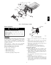
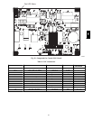
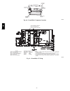
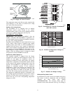
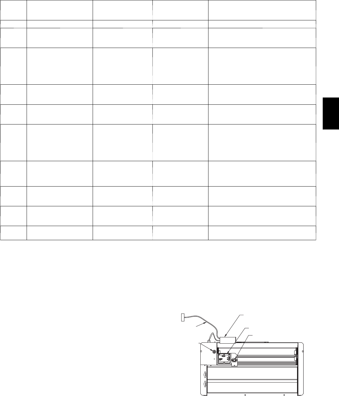
ECONOMIZER SYSTEMS
The 580J units may be equipped with a factory--installed
or accessory (field--installed) economizer system. Two
types are available: with a logic control system
(EconoMi$er IV) a nd without a control system
(EconoMi$e r2). See Fig. 39 and Fig. 40 for component
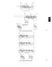
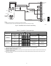
locations on each type. See Fig. 41 and Fig. 42 for
economizer section wiring diagrams.
Both economizers use direct-- drive damper actuators.
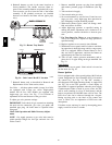
ECONOMI$ER IV
CONTROLLER
OUTSIDE AIR
TEMPERATURE SENSOR
LOW AMBIENT
SENSOR
A
CTUATOR
WIRING
HARNESS
C06021
Fig. 39 -- EconoMi$er IV Component Locations
580J