


15
CONVENIENCE OUTLETS
ELECTRICAL OPERATION HAZARD
Failure to foll ow this warning could result in personal
injury or death.
Units with conveni ence out let circuits may use
multiple disconnects. Check convenience outlet for
power status before ope ning unit for service. Locate
its disconnect switch, if appropriate, and open it.
Tag-- out this switch, if necessary.
!
WARNING
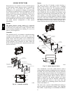
Two types of convenience outlets are offered on 580J
models: Non--powered and unit--powered. Both types
provide a 125--volt GFCI (ground--fault
circuit --interrupter) duplex receptacle rated at 15--A
behind a hinged waterproof access cover, located on the
end panel of the unit. See Fig. 14.
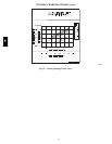
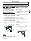
Pwd-CO Transformer
Conv Outlet
GFCI
Pwd-CO
Fuse
Switch
C08128
Fig. 14 -- Convenience Outlet Location
Non--powered type: This type requires the fiel d
installation of a ge neral --purpose 125--volt 15--A circuit
powered from a source elsewhere i n the building. Observe
national and local codes when selecting wire size, fuse or
breake r requirements and disconnect switch size and
loca tion. Route 125--v power supply conductors into the
bottom of the utility box containing the duplex receptacle.
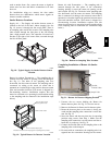
Unit--powered type: A unit--mounted transformer is
fact ory--installed to stepdown the main power supply
voltage to the unit to 115--v at the duplex receptacle. This
option also includes a manual switch with fuse, located in
a utility box and m ounted on a bracket behind the
convenience outlet; access is through the unit’s control
box access panel. See Fig. 14.
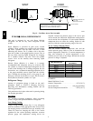
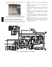
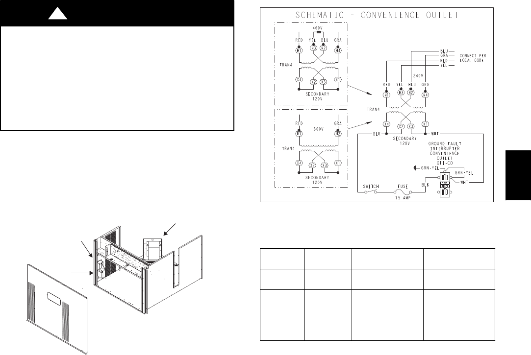
The primary leads to the convenience outl et transformer
are not factory--connected. Selection of primary power
source is a customer--option. If local codes permit, the
transformer primary leads can be connected at the
line--side t erminals on a unit--mounted non--fused
disconnec t or HACR breaker switch; this will provide
service power to the unit when the unit disconnect switch
or HACR switch is ope n. Other connection methods will
result in the convenience outl et circuit being de--energized
when the unit disconnect or HACR switch is open. See
Fig. 15.
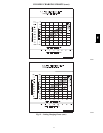
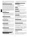
CO8283
Fig. 15 -- Powered Convenience Outlet Wiring
UNIT
VOLTAGE
CONNECT
AS
PRIMARY
CONNECTIONS
TRANSFORMER
TERMINALS
208,
230
240
L1: RED +YEL
L2: BLU + GRA
H1 + H3
H2 + H4
460 480
L1: RED
Splice BLU + YEL
L2: GRA
H1
H2 + H3
H4
575 600
L1: RED
L2: GRA
H1
H2
Duty Cycle: The unit--powered convenience outlet has a
duty cycle limitation. The transformer is intended to
provide power on an intermittent basis for service tools,
lamps, etc; it is not intended to provide 15 --amps loading
for continuous duty l oads (such as e lectric heaters for
overnight use). Observe a 50% limit on circuit loading
above 8--amps (i.e., limit loads exceeding 8--amps to 30
minutes of operation every hour).
Maintenance: Periodically test the GFCI receptacle by
pressing the TEST button on the face of the receptacle.
This should cause the internal circuit of the receptacle to
trip and open the receptacle. Check for proper grounding
wires and power line phasing if the GFCI receptacle does
not trip a s required. Press the RESET button to clear the
tripped condition.
Fuse on powered type: The factory fuse is a Bussman
“Fusetron” T--15, non--renewable screw--in (Edison ba se)
type plug fuse.
Using unit--mount ed convenience outlets: Units with
unit--mounted convenience outlet circuits will often
require that two disconnects be opened to de--energize all
power to the unit. Treat all units as electrically energized
until the convenience outlet power is also checked and
de--energization is confirmed. Observe National Electrical
Code Article 210, Branch Circuits, for use of convenience
outlets.
580J