


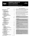
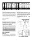
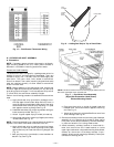
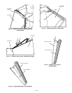
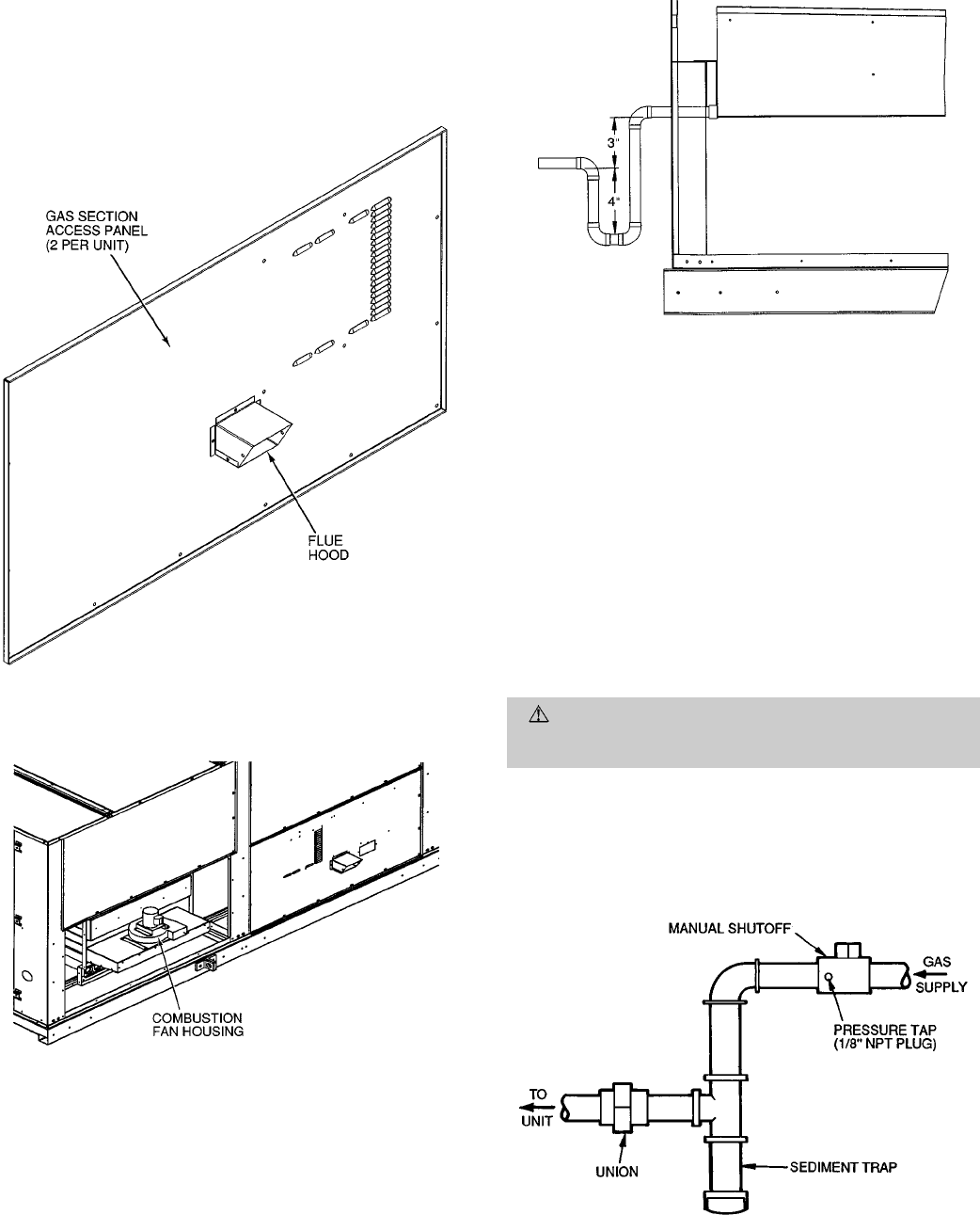
V. FLUE HOOD
Flue hood is shipped inside gas section of unit. To install, se-
cure flue hood to access panel. See Fig. 7.
NOTE: When properly installed, flue hood will line up with
combustion fan housing. See Fig. 8.
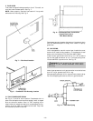
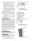
VI. TRAP CONDENSATE DRAIN
See Fig. 2, 3, and 9 for drain location. Condensate drain is
open to the atmosphere and must be trapped. Install a trapped
drain at the drain location. One 1-in. NPT coupling is pro-
vided inside unit evaporator section for condensate drain con-
nection. A trap at least 4-in. deep must be used. Trap must
be installed to prevent freeze-up.
Condensate pans are sloped so that water willcompletely drain
from the condensate pan to comply with indoor air quality
guidelines.
VII. GAS PIPING
Unit is equipped for use with natural gas. Installation must
conform with local building codes or, in the absence of local
codes, with the National Fuel Gas Code, ANSI Z223.1.
Install manual gas shutoff valve with a
1
⁄
8
-in. NPT pressure
tap for test gage connection at unit. Field gas piping must
include sediment trap and union. See Fig. 10.
WARNING:
Do not pressure test gas supply while
connected to unit. Always disconnect union before
servicing.
Natural gas pressure at unit gas connection must not be less
than 5 in. wg or greater than 13.5 in. wg.
Size gas-supply piping for 0.5-in. wg maximum pressure drop.
Do not use supply pipe smaller than unit gas connection.
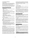
Fig. 7 — Flue Hood Location
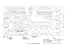
Fig. 8 — Combustion Fan Housing Location
Fig. 9 — Condensate Drain Connections
(Typical Roof Curb or
Slab Mount Shown)
Fig. 10 — Field Gas Piping
—8—