


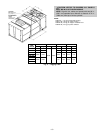
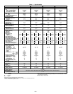
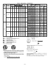
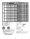

Table 1 — Specifications
UNIT 580G,H 240 300 324 360
NOMINAL CAPACITY (tons) 20 25 27 30
OPERATING WEIGHT (lb)
Unit
Al/Al* (Lo Heat/Hi Heat) 4176/4256 4262/4342 4262/4342 4262/4342
Al/Cu* (Lo Heat/Hi Heat) 4396/4476 4482/4562 4482/4562 4482/4562
Roof Curb (14-in. curb) 365 365 365 365
COMPRESSOR
Type Ckt 1 06D328 06D328 06D537 06D537
Ckt 2 06D818 06D328 06D328 06D537
Number of Refrigerant Circuits 22 2 2
Oil (oz) (Ckt 1, Ckt 2) 115, 88 115 ea. 115 ea. 115 ea.
REFRIGERANT TYPE R-22
Operating Charge (lb-oz)
Circuit 1† 25-0 25-0 25-0 25-0
Circuit 2 31-0 25-0 25-0 25-0
CONDENSER COIL Cross-Hatched
3
⁄
8
Љ Copper Tubes, Aluminum Lanced,Aluminum Pre-Coated, or Copper Plate Fins
Quantity 11 1 1
Rows...Fins/in. 4...15 4...15 4...15 4...15
Total Face Area (sq ft) 33.3 33.3 33.3 33.3
CONDENSER FAN Propeller Type
Nominal Cfm 13,420 13,420 13,420 13,420
Quantity...Diameter (in.) 2...30 2...30 2...30 2...30
Motor Hp (1075 Rpm) 11 1 1
EVAPORATOR COIL Cross-Hatched
3
⁄
8
Љ Copper Tubes, Aluminum Plate Fins, Intertwined Circuits
Rows...Fins/in. 4...15 4...15 4...15 4...15
Total Face Area (sq ft) 31.7 31.7 31.7 31.7
EVAPORATOR FAN Centrifugal Type
Quantity...Size (in.) 2...20x15 2...20x15 2...20x15 2...20x15
Type Drive Belt Belt Belt Belt
Nominal Cfm 8,000 10,000 11,000 12,000
Motor Hp 5 10** 15 7.5 10** 15 10 15** 20 10 15** 20
Motor Frame Size
Standard S184T S215T D254T S213T S215T D254T S215T D254T S256T S215T D254T S256T
High Efficiency S184T S215T S254T S213T S215T S254T S215T S254T S256T S215T S254T S256T
Motor Bearing Type Ball Ball Ball Ball
Maximum Allowable Rpm 1200 1200 1200 1200
Motor Pulley Pitch Diameter 4.8 4.4 5.7 5.4 6.1 5.5 4.4 4.9 5.9 4.4 5.7 5.9
Nominal Motor Shaft Diameter (in.) 1
1
⁄
8
1
3
⁄
8
1
5
⁄
8
1
3
⁄
8
1
3
⁄
8
1
5
⁄
8
1
3
⁄
8
1
5
⁄
8
1
5
⁄
8
1
3
⁄
8
1
5
⁄
8
1
5
⁄
8
Fan Pulley Pitch Diameter (in.) 12.4 8.6 9.1 12.4 11.1 8.7 9.4 8.1 8.7 9.0 9.1 8.7
Nominal Fan Shaft Diameter (in.) 1
15
⁄
16
1
15
⁄
16
1
15
⁄
16
1
15
⁄
16
Belt, Quantity...Type
Belt, Length (in.)
1...BX59
62
2...BX51
54
2...5VX530
53
1...BX59
62
1...5VX590
59
2...5VX530
53
2...BX52
55
2...5VX500
50
2...5VX530
53
2...BX51
54
2...5VX530
53
2...5VX530
53
Pulley Center Line Distance (in.) 16.0-18.7 15.6-18.4 15.0-17.9 15.6-18.4 15.0-17.9 15.6-18.4 15.0-17.9 15.6-18.4 15.0-17.9
Factory Speed Setting (rpm) 717 924 1096 773 962 1106 848 1059 1187 884 1096 1187
FURNACE SECTION
Rollout Switch Cutout Temp (F)†† 225 225 225 225
Burner Orifice Diameter
(in. ...drill size)
Natural Gas Std .111...34 .111...34 .111...34 .111...34
Liquid Propane Alt .089...43 .089...43 .089...43 .089...43
Thermostat Heat Anticipator
Setting (amps)
Stage 1 0.1 0.1 0.1 0.1
Stage 2 0.1 0.1 0.1 0.1
Gas Input (Btuh) Stage 1 Low 262,500 262,500 262,500 262,500
High 394,000 394,000 394,000 394,000
Stage 2 Low 350,000 350,000 350,000 350,000
High 525,000 525,000 525,000 525,000
Efficiency (Steady State) (%) 82 82 82 82
Temperature Rise Range 15-45/35-65 15-45/35-65 15-45/35-65 15-45/35-65
Manifold Pressure (in. wg)
Natural Gas Std 3.5 3.5 3.5 3.5
Liquid Propane Alt 3.5 3.5 3.5 3.5
Gas Valve Quantity 22 2 2
Field Gas Connection Size
(in.-FPT)
1.5 1.5 1.5 1.5
HIGH-PRESSURE SWITCH (psig)
Cutout 426 426 426 426
Reset (Auto.) 320 320 320 320
LOW-PRESSURE SWITCH (psig)
Cutout 77 7 7
Reset (Auto.) 22 22 22 22
RETURN-AIR FILTERS
Quantity...Size (in.) 10...20x24x2 10...20x24x2 10...20x24x2 10...20x24x2
OUTDOOR-AIR FILTERS 8...16×25
Quantity...Size (in.) 4...20×25
POWER EXHAUST Direct Drive, 3-Speed, Single Phase Motor (Factory Wired for High Speed), Forward-Curved Fan
Motor, Quantity...Hp 4...1
Fan, Diameter...Width (in.) 11...10
LEGEND
Al — Aluminum
Cu — Copper
*Evaporator coil fin material/condenser coil fin material.
†Circuit 1 uses the lower portion ofcondenser coil; Circuit 2 uses the upper portion.All
units have intertwined evaporator coils.
**Motor and drive shown willdeliver approximately 2.5 in. net externalstatic. For more
fan motor data, see Table 2.
††Rollout switch is manual reset.
—6—