


3. Mount the outdoor air enthalpy sensor inside the right
economizer hood on the right side panel of the hood,
adjacent to the outdoor-air thermistor.
4. Locate the red, violet, and brown wires near the out-
door air thermistor. Remove the splice from the red and
violet wires. Remove the cap from the brown wire.
5. Install a
1
⁄
4
-in. push on terminal (field-supplied) on the
violet and brown wires.
6. Connect a
1
⁄
4
-in. push on terminal (field-provided) to one
end of a 18-gage, 6-in. jumper wire (field-provided). Con-
nect the other end to the red wire and attach a
1
⁄
4
-in.
push on connector (field-provided).
7. Connect the red wire with the jumper to terminal TR1.
Connect the jumper to terminal 2. Connect the brown
wire to terminal TR. Connect the violet wire to termi-
nal 3. All connections are on the enthalpy control.
8. Replace the economizer filters.
9. Return power to unit.
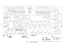
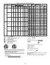
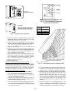
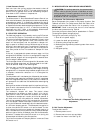
Accessory Differential Enthalpy Control (Fig. 26)
The control (HH57AC077), in conjunction with the accessory
enthalpy sensor (HH57AC078), controls economizer opera-
tion according to the differential enthalpy. The control is
mounted in the economizer hood. The sensor is mounted in
the return duct (580G) or the return air plenum (580H).
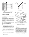
Differential Enthalpy Sensor Installation
To install the control, perform the following procedure:
1. Turn off all power. Ensure disconnect is locked out.
2. Remove the economizer inlet filters from the bottom of
the right hand economizer hood.
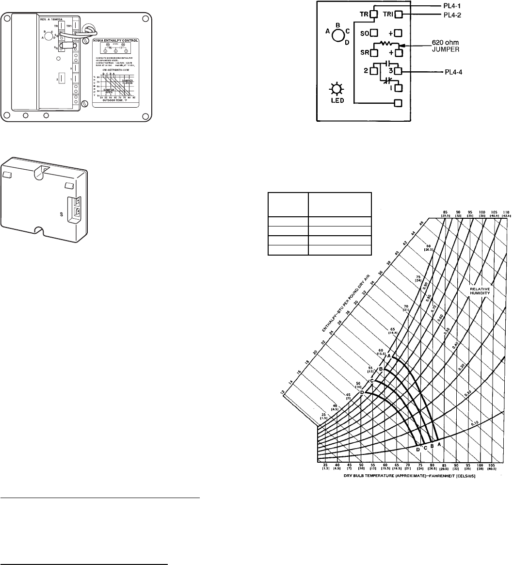
3. Remove the factory-installed, 620-ohm jumper be-
tween terminals SR and + on the enthalpy control
located inside the outdoor air hood.
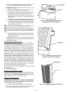
4. Connect the violet wire from the enthalpy sensor kit to
the + terminal on the enthalpy control. Connect the blue
wire from the enthalpy sensor kit to the SR terminal
on the terminal control.
5. Turn the enthalpy control set point potentiometer clock-
wise past the ‘‘D’’setting on the enthalpy control to con-
figure the control to operate on differential enthalpy.
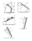
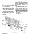
6. Remove the return-air enthalpy sensor from the acces-
sory package. Using the screws provided, mount the
sensor inside the return duct near the unit. Do not
locate the control too far from the unit, or the wires
will not reach from the sensor to the control. On 580H
units, the enthalpy sensor can be installed in the
return air section of the unit, under the return air
dampers.
7. Route the wires from the enthalpy sensor to the
return air enthalpy control through the holes on the
inside of the hinged filter access panel. The holes are
blocked by plug buttons which should be removed.
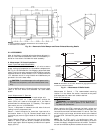
+
C7400A1004
Fig. 26 — Enthalpy Control and Sensor
HH57AC077
ENTHALPY CONTROL
HH57AC078
ENTHALPY SENSOR (USED WITH
ENTHALPY CONTROLFORDIFFER-
ENTIAL ENTHALPY OPERATION)
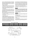
NOTE: Switches shown in high enthalpy state. Termi-
nals 2 and 3 close on enthalpy decrease.
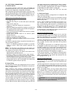
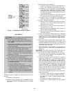
Fig. 27 — Wire Connections for Solid-State
Enthalpy Control (HH57AC077)
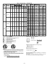
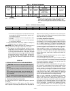
CONTROL
CURVE
CONTROL POINT
(APPROX. DEG.)
AT 50% RH
A 73 (23)
B 70 (21)
C 67 (19)
D 63 (17)
RH — Relative Humidity
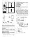
Fig. 28 — Psychrometric Chart for Enthalpy Control
—17—