


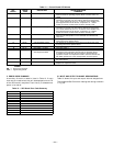
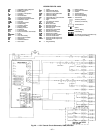
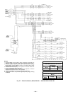
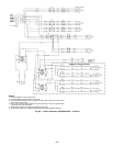
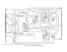

LEGEND FOR FIG. 46-50
AHA — Adjustable Heat Anticipator
BP — Building Pressure
BR — Burner Relay
C—Contactor, Compressor
CAP — Capacitor
CB — Circuit Breaker
CC — Cooling Compensator
CCB — Compressor Circuit Breaker
CCH — Crankcase Heater
COM — Common
COMP — Compressor Motor
CR — Control Relay
CV — Constant Volume
DM — Damper Motor
EC — Enthalpy Control
EQUIP — Equipment
FLA — Full Load Amps
FPT — Freeze Protection Thermostat
FU — Fuse
GND,GRD — Ground
GVR — Gas Valve Relay
HPS — High-Pressure Switch
HR — Heat Relay
HS — Hall Effect Sensor
HV — Heat Valve
I—Ignitor
IDM — Induced-Draft Motor
IFC — Indoor Fan Contactor
IFCB — Indoor Fan Circuit Breaker
IFM — Indoor-Fan Motor
IFR — Indoor-Fan Relay
IGC — Integrated Gas Unit Controller
IP — Internal Protector
L—Light
LPS — Low-Pressure Switch
LS — Limit Switch
MGV — Main Gas Valve
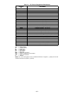
NC — Normally Closed
NEC — National Electrical Code
NO — Normally Open
OAT — Outdoor-Air Thermostat
OD — Outside Diameter
OFC — Outdoor-Fan Contactor
OFM — Outdoor-Fan Motor
PEC — Power Exhaust Contactor
PEM — Power Exhaust Motor
PES — Power Exhaust Sequencer
PESC — Power Exhaust Sequencer
Controller
PL — Plug Assembly
RS — Rollout Switch
SAT — Supply-Air Thermistor
SW — Switch
TB — Terminal Block
TC — Thermostat Cooling
TH — Thermostat Heating
TRAN — Transformer
Terminal (Marked)
Terminal (Unmarked)
Terminal Block
Splice
Factory Wiring
Field Wiring
To Indicate Common Potential Only,
Not To Represent Wiring
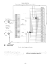
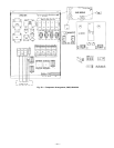
Fig. 46 — 115 V Control Circuit Schematic; 580G,H240-360
—37—