


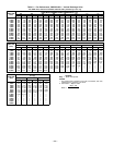
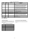
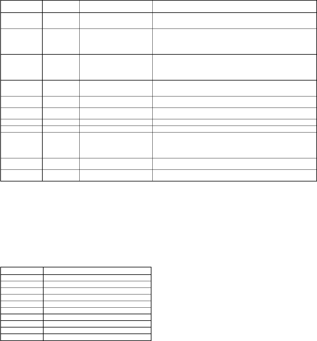
Table 12 — Control Board LED Alarms
LED
BLINKS
ERROR
CODE
DESCRIPTION
TROUBLESHOOTING
COMMENTS
1 Normal Operation The control board flashes the red LED in one-second intervals
when the board is operating properly. Make sure DIP switch 3 is
closed.
2 HF-13 Compressor 1 Safety The high or low pressure safety switch for compressor no. 1 has
opened for 3 seconds. The error will be cleared and compressor
no. 1 will be allowed to turn on in 15 minutes. If the safeties have
been tripped 3 times in 90 minutes, compressor no. 1 will be
locked out until the control board has been manually reset.
3 HF-14 Compressor 2 Safety The high or low pressure safety switch for compressor no. 2 has
opened for 3 seconds. The error will be cleared and compressor
no. 2 will be allowed to turn on in 15 minutes. If the safeties have
been tripped 3 times in 90 minutes, compressor no. 2 will be
locked out until the control board has been manually reset.
4 HF-15 Thermostat Failure The thermostat is calling for both heating and cooling at the same
time. The unit will operate on a first call basis and will automati-
cally reset.
5 HF-05 SAT Thermistor Failure The supply-air temperature (SAT) sensor has failed. First check for
wiring errors, then replace sensor.
6 HF-06 OAT Thermistor Failure The outside-air temperature (OAT) sensor has failed. First check
for wiring errors, then replace sensor.
7 HF-03 DIP Switch 2 is Open Close DIP switch 2.
8 HF-12 DIP Switch 1 is Open Close DIP switch 1.
9 SE-05 Loss of Communications
with Expansion Board
Communications between the expansion board and the control
board have been interrupted. Ensure that an expansion board
is installed and wired using the wire harness supplied with the
expansion module. If an expansion board is not used, ensure that
DIP switch position 3 is in the closed position and reset power.
10 HF-16 Control Board Failure Generated when hardware has failed on control board. Replace
the control board.
11 HF-17 Expansion Board Failure Generated when hardware has failed on the expansion board.
Replace the expansion board.
LEGEND
DIP — Dual In-Line Package
LED — Light-Emitting Diode
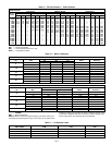
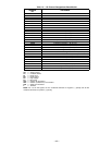
II. ERROR CODE SUMMARY
A summary of the error codes is listed in Table 13. If more
than one error code exists, they will be displayed on the LED
of the IGC board in sequence. Fault history is deleted when
power is turned off.
Table 13 — IGC Board Error Code Summary
INDICATION ERROR MODE
ON NORMAL OPERATION
OFF HARDWARE FAILURE
1 FLASH FAN ON/OFF DELAY MODIFIED
2 FLASHES LIMIT SWITCH FAULT
3 FLASHES FLAME SENSE FAULT
4 FLASHES 4 CONSECUTIVE LIMIT SWITCH FAULTS
5 FLASHES IGNITION LOCKOUT FAULT
6 FLASHES INDUCED DRAFT MOTOR FAULT
7 FLASHES ROLLOUT SWITCH FAULT
8 FLASHES INTERNAL CONTROL FAULT
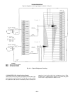
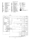
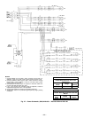
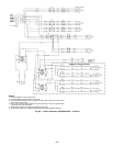
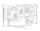
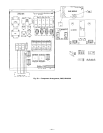
III. INPUT AND OUTPUT CHANNEL DESIGNATIONS
Table 14 shows the input and output channel designations.
The Integrated Gas Controls for heating and cooling are shown
in Fig. 45.
—34—