


SERVICE
WARNING:
Before beginning any maintenance, be
sure to turn off power at the main disconnect switch.
TAG THE SWITCH WITH A SUITABLE WARNING
LABEL.
All unit components can be reached through clearly labelled
hinged access doors. These doors are not equipped with tie-
backs, so if heavy duty servicing is needed, either remove them
or prop them open to prevent accidental closure.
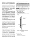
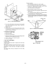
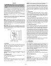
Each door is held closed with 3 latches. The latches are se-
cured to the unit with a single
1
⁄
4
-in.-20x
1
⁄
2
-in. long bolt.
See Fig. 39.
To open, loosen the latch bolt using a
7
⁄
16
-in. wrench. Pivot
the latch so it is not in contact with the door. Open the door.
To shut, reverse the above procedure.
NOTE: Disassembly of the top cover may be required under
special service circumstances. It is very important that the
orientation and position of the top cover be marked on the
unit prior to disassembly. This will allow proper replacement
of the top cover onto the unit and prevent rainwater from
leaking into the unit.
IMPORTANT: After servicing is completed, make sure door
is closed and relatched properly, and that the latches are tight.
Failure to do so can result in water leakage into the evapo-
rator section of the unit.
I. CLEANING
Inspect unit interior at beginning of each heating and cool-
ing season and as operating conditions require. Remove unit
top panel and/or side panels for access to unit interior.
A. Evaporator Coil
Clean as required with a commercial coil cleaner.
B. Condenser Coil
Clean condenser coil annually and as required by location and
outdoor-air conditions. Inspect coil monthly — clean as
required.
C. Condensate Drain
Check and clean each year at start of cooling season. In win-
ter, keep drains and traps dry.
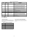
D. Filters
Clean or replace at start of each heating and cooling season,
or more often if operating conditions require. Refer to
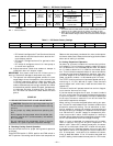
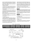
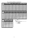
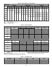
Table 1 for type and size.
NOTE: The unit requires industrial grade throwaway filters
capable of withstanding face velocities up to 625 fpm.
To replace filters, open filter access door (marked with label).
Remove inner access panel. Remove plastic filter retainer in
between filter tracks by sliding and pulling outward. Remove
first filter by sliding out opening in filter track. Locate filter
removal tool, which is shipped next to the return air damp-
ers. Use the filter removal tool to remove the rest of the
filters.
E. Main Burners
At the beginning of each heating season, inspect for deterio-
ration or blockage due to corrosion or other causes. Observe
the main burner flames and adjust if necessary. Refer to Main
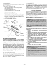
Burners sections on page 28. Check spark gap. See Fig. 40.
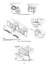
F. Flue Gas Passageways
The flue collector box and heat exchanger cells may be
inspected by removing gas section access panel (Fig. 2 and
3), flue box cover, collector box, and main burner assembly
(Fig. 41 and 42). Refer to Main Burners section on page 28
for burner removal sequence. If cleaning is required, clean
all parts with a wire brush. Reassemble using new cerafelt
high-temperature insulation for sealing.
G. Combustion-Air Blower
Clean periodically to assure proper airflow and heating effi-
ciency. Inspect blower wheel every fall and periodically dur-
ing heating season. For the first heating season, inspect blower
wheel bi-monthly to determine proper cleaning frequency.
To inspect blower wheel, remove heat exchanger access panel.
Shine a flashlight into opening to inspect wheel. If cleaning
is required, remove motor and wheel assembly by removing
screws holding motor mounting plate to top of combustion fan
housing (Fig. 41 and 42). The motor, scroll, and wheel assem-
bly can be removed from the unit. Remove scroll from plate.
Remove the blower wheel from the motor shaft and clean with
a detergent or solvent. Replace motor and wheel assembly.
H. Outdoor-Air Inlet Screens
Clean screens with steam or hot water and a mild detergent.
Do not use throwaway filters in place of screens.
II. LUBRICATION
A. Compressors
Each compressor is charged with the correct amount of oil
at the factory. The correct oil charge is shown in Table 1. If
oil is visible in the compressor sight glass, check unit for
operating readiness as described in Start-Up section,then start
the unit. Observe oil level and add oil, if required, to bring oil
level in compressor crankcase up to between
1
⁄
4
and
1
⁄
3
of sight
glass during steady operation.
If oil charge is above
1
⁄
3
sight glass, do not remove any oil
until the compressor crankcase heater has been energized for
at least 24 hours with compressor off.
When additional oil or a complete charge is required, use only
approved compressor oils:
Petroleum Specialties, Inc. ...................Cryol 150
Texaco, Inc. ...........................Capella WF-32
Witco Chemical Corp. .....................Suniso 3GS
IMPORTANT: Do not use reclaimed oil or oil that has been
exposed to the atmosphere. Refer to Standard Service Tech-
niques Manual, Chapter 1, Refrigerants section, for proce-
dures to add or remove oil.
Fig. 39 — Door Latch
—29—