


compressor 2 will turn on. If Y2 is deenergized at any time,
only the last stage of compression that was energized will be
turned off. If outdoor conditions are not suitable for econo-
mizer cooling, the economizer will go to minimum position
and cycle compressors 1 and 2 based on demand from Y1 and
Y2 respectively. The compressors will be locked out when the
SAT temperature is too low (less than 40 F for compressor 1
and less than 45 F for compressor 2.) After a compressor is
locked out, it can restart after normal time-guard period.
The compressor time delay function maintains a minimum
off time of 5 minutes, a minimum on time of 10 seconds, and
a minimum delay before starting the second compressor of
10 seconds.
When heating, the heat stages respond to the demand
from W1 and W2 of the thermostat input. Heating and cool-
ing will be mutually locked-out on demand on a first call
basis. The heating and the cooling functions cannot operate
simultaneously.
C. Cooling Capacity Control
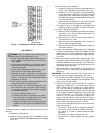
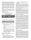
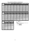
The cooling capacity staging is shown in Table 6.
Table 6 — Cooling Capacity Staging Table,
Units with 2 Compressors
STAGES 0
1
ECONOMIZER
23
Compressor 1 Off Off On On
Compressor 2 Off Off Off On
NOTE: On units which require additional unloading, add suction pres-
sure unloaders to compressor no. 1 only.
II. HEATING SECTION START-UP AND ADJUSTMENTS
CAUTION:
Complete the required procedures given
in the Pre-Start-Up section on page 20 before starting
unit. Do not jumper any safety devices when operating
the unit.
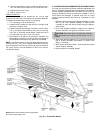
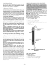
Verify gas pressures before turning on heat as follows:
a. Turn off manual gas stop.
b. Connect pressure gage to supply gas tap (See Fig. 10
on page 8).
c. Connect pressure gage to manifold pressure tap on
gas valve.
d. Supply gas pressuremust not exceed 13.5 in. wg.Check
pressure.
e. Turn on manual gas stop and set thermostat to HEAT
position. After the unit has run for several minutes,
verify that incoming pressure is 5.0 in. wg or greater,
and that the manifold pressure is 3.5 in. wg. If mani-
fold pressure must be adjusted, refer to Gas Valve
Adjustment section on page 25.
A. Checking Heating Control Operation
Start and check the unit for proper heating control operation
as follows:
1. Turn on manual gas stop.
2. Set thermostat setting to HEAT position.
3. The evaporator fan and first-stage heat will start im-
mediately. If unit is equipped with 2 heaters, second-
stage heat will energize upon a call for additional heat.
Check for heating effect at supply diffusers.
4. The evaporator fan and heaters will cycle off with no
delay after thermostat temperature is satisfied.
B. Gas Heating
The gas heat units incorporate two separate systems to pro-
vide gas heat. Each system incorporates its own induced draft
motor, Integrated Gas Control (IGC) board, 2-stage gas valve,
manifold, etc. The systems are operated in parallel, for
example, when there is a call for first stage heat, both
induced draft motors operate, both gas valves are energized
and both IGC boards initiate spark.
All of the gas heating control is performed through the IGC
boards. The base module board serves only to initiate and
terminate heating operation.
The base module board is powered by 24 vac. When the ther-
mostat or room sensor calls for heating, power is sent from
the base module board to W on each of the IGC boards. A
light-emitting diode (LED) on the IGC board will be on dur-
ing normal operation. Acheck is made to ensure that the roll-
out switches and limit switches are closed and the induced
draft motors are not running. The induced-draft motors are
then energized and when speed is proven with the hall effect
sensor on the motor, the ignition activation period begins. The
burners will ignite within 5 seconds.
When ignition occurs the IGC board will continue to monitor
the condition of the rollout and limit switches, the hall effect
sensor as well as the flame sensor. If the unit is controlled
through a room thermostat set for fan auto., 45 seconds after
ignition occurs, the indoor-fan motor will be energized and
the outdoor-air dampers will open to their minimum posi-
tion. If for some reason the overtemperature limit opens prior
to the start of the indoor fan blower, on the next attempt, the
45-second delay will be shortened to 5 seconds less than the
time from initiation of heat to when the limit tripped. Gas
will not be interrupted to the burners and heating will con-
tinue. Once modified, the fan on delay will not change back
to 45 seconds unless power is reset to the control.
When additional heat is required,W2 closes and initiates power
to the second stage of the main gas valves. When the ther-
mostat is satisfied, W1 and W2 open and the gas valves close
interrupting the flow of gas to the main burners. If the call
for W1 lasted less than 1 minute, the heating cycle will not
terminate until 1 minute after W1 became active. If the unit
is controlled through a room thermostat set for fan auto., the
indoor-fan motor will continue to operate for an additional
45 seconds then stop and the outdoor-air dampers will close.
If the over-temperature limit opens after the indoor motor is
stopped within 10 minutes of W1 becoming inactive, on the
next cycle the time will be extended by 15 seconds. The maxi-
mum delay is 3 minutes. Once modified, the fan off delay will
not change back to 45 seconds unless power is reset to the
control.
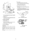
C. Power Exhaust Operation
The optional power exhaust packages are factory- or field-
installed with vertical units and optionally installed in the
return air ductwork for horizontal applications. The stand-
ard and the modulating power exhaust (used with non-
modulatng to modulating conversion package) are the two
packages offered. The modulating power exhaust package is
equipped with a field-adjustable static pressure controller to
stage up to 4 power exhaust stages which will maintain a
building static pressure. The blue controller located in the
control box below the control board can be adjusted, by
removing the covers and adjusting the set point dial to
the desired building pressure. The blue controller monitors
the 4 individual sequencers which activate the 4 individual
power exhaust motors. The standard power exhaust package
—22—