


INSTALLATION
I. PROVIDE UNIT SUPPORT
CAUTION:
All panels must be in place when rig-
ging. Unit is not designed for handling by fork truck.
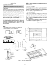
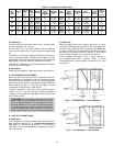
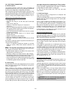
A. Roof Curb
Assemble and install accessory roof curb in accordance with
instructions shipped with the curb. Accessory roof curb and
information required to field fabricate a roof curb or horizon-
tal adapter are shown in Fig. 1. Install insulation, cant strips,
roofing, and counter flashing as shown. Ductwork can be
secured to roof curb before unit is set in place.
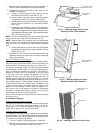
IMPORTANT: The gasketing of the unit to the roof curb is
critical for a leak-proof seal. Install gasket supplied with the
roof curb as shown in Fig. 1. Improperly applied gasket can
result in air leaks and poor unit performance.
Curb should be level. This is necessary to permit unit drain
to function properly. Unit leveling tolerance is shown in
Fig 1. Refer to Accessory Roof Curb Installation Instructions
for additional information as required. When accessory roof
curb is used, unit may be installed on class A, B, or C roof
covering material.
NOTE: On retrofit jobs, ductwork may be attached to old unit
instead of roof curb. Be careful not to damage ductwork when
removing old unit.
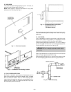
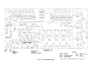
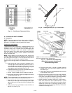
B. Alternate Unit Support
When the preferred curb or adapter cannot be used, support
unit with sleepers using unit curb or adapter support area. If
sleepers cannot be used, support long sides of unit (refer to
Fig. 2 and 3) with 3 equally spaced 4-in. x 4-in. pads on each
side. Unit may sag if supported by corners only.
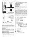
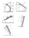
II. RIG AND PLACE UNIT
Inspect unit for transportation damage. File any claim with
transportation agency. Keep unit upright, and do not drop.
Use spreader bars over unit to prevent sling or cable dam-
age. Rollers may be used to move unit across a roof. Level by
using unit frame as a reference; leveling tolerance is shown
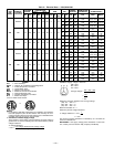
in. Fig. 1. See Fig. 4 for additional information. Unit weight
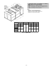
is shown in Table 1.
Four lifting lugs are provided on the unit base rails as shown
in Fig. 4. Refer to rigging instructions on unit.
(Copy continued on page 7.)
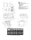
NOTE: To prevent standing water in the drain pan of the
indoor section and the heat exchangers, UNIT CAN ONLY BE
PITCHED AS SHOWN.
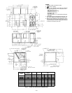
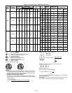
NOTES:
1. Unless otherwise specified, all dimensions are to outside of part.
2. Roof curb accessory is shipped disassembled.
3. All roof curb parts are to be 16 ga galvanized steel.
4. Dimensions are in inches.
UNIT LEVELING TOLERANCES
DIMENSIONS*
(Degrees and Inches)
AB
Deg. in. Deg. in.
1.0 2.9 .50 .75
*From edge of unit to horizontal.
Fig. 1 — Roof Curb (Sizes 240-360)
—2—