


B. Fan Shaft Bearings
Lubricate the bearings at least twice annually with suitable
bearing grease. Do notover grease. Typical lubricants are shown
below:
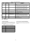
MANUFACTURER LUBRICANT
Texaco Regal AFB-2*
Mobil Mobilplex EP No. 1
Sunoco Prestige 42
Texaco Multifak 2
*Preferred lubricant because it contains rust and oxidation inhibitors.
C. Condenser and Evaporator-Fan Motor Bearings
The condenser and evaporator-fan motors have permanently-
sealed bearings, so no field lubrication is necessary.
III. EVAPORATOR FAN SERVICE AND REPLACEMENT
1. Turn off unit power.
2. Remove supply-air section panels.
3. Remove belt and blower pulley.
4. Loosen setscrews in blower wheels.
5. Remove locking collars from bearings.
6. Remove shaft.
7. Remove venturi on opposite side of bearing.
8. Lift out wheel.
9. Reverse above procedure to reinstall fan.
10. Check and adjust belt tension as necessary.
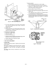
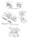
IV. EVAPORATOR-FAN MOTOR REPLACEMENT
1. Shut off unit power supply.
2. Remove upper outside panel and open hinged door to
gain access to motor.
3. Fully retract motor plate adjusting bolts.
4. Loosen the 2 rear (nearest the evaporator coil) motor
plate nuts.
5. Remove the 2 front motor plate nuts and carriage bolts.
6. Slide motor plate to the rear (toward the coil) and
remove fan belt(s).
7. Slide motor plate to the front and hand tighten one of
the rear motor plate nuts (tight enough to prevent the
motor plate from sliding back but loose enough to al-
low the plate to pivot upward).
8. Pivot the front of the motor plate upward enough to
allow access to the motor mounting hex bolts and
secure in place by inserting a prop.
9. Remove the nuts from the motor mounting hex bolts
and remove motor.
10. Reverse above steps to install new motor.
V. POWER FAILURE
Dampers have a spring return. In eventof power failure, damp-
ers will return to fully closed position until power is restored.
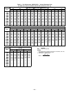
VI. REFRIGERANT CHARGE
Amount of refrigerant charge is listed on unit nameplate and
in Table 1. Refer to GTAC II; Module 5; Charging, Recovery,
Recycling, and Reclamation section for charging methods and
procedures.
Unit panels must be in place when unit is operating during
charging procedure.
A. No Charge
Use standard evacuating techniques. After evacuating sys-
tem, weigh in the specified amount of refrigerant (refer to
Table 1).
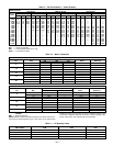
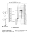
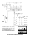
B. Low Charge Cooling
Using appropriate cooling charging chart (see Fig. 43), add
or remove refrigerant until conditions of the appropriate chart
are met. Note that charging chart is different from those
normally used. An accurate pressure gage and temperature
sensing device are required. Measure liquid line pressure
at the liquid line service valve using pressure gage. Connect
temperature sensing device to liquid line near the liquid line
service valve and insulate it so that outdoor ambient tem-
perature does not affect reading. Indoor-air cfm must be within
normal operating range of unit. Take outdoor ambient tem-
perature and read the suction pressure gage. Refer to appro-
priate chart to determine correct suction temperature. If
intersection point on chart is above the curve, add refrig-
erant. If intersection point on chart is below curve, carefully
recover some of the charge. Recheck suction pressure as charge
is adjusted.
Fig. 43 — Cooling Charging Chart,
580G,H240-360
—31—