


TROUBLESHOOTING
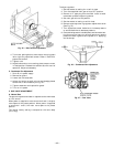
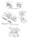
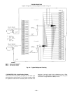
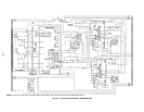
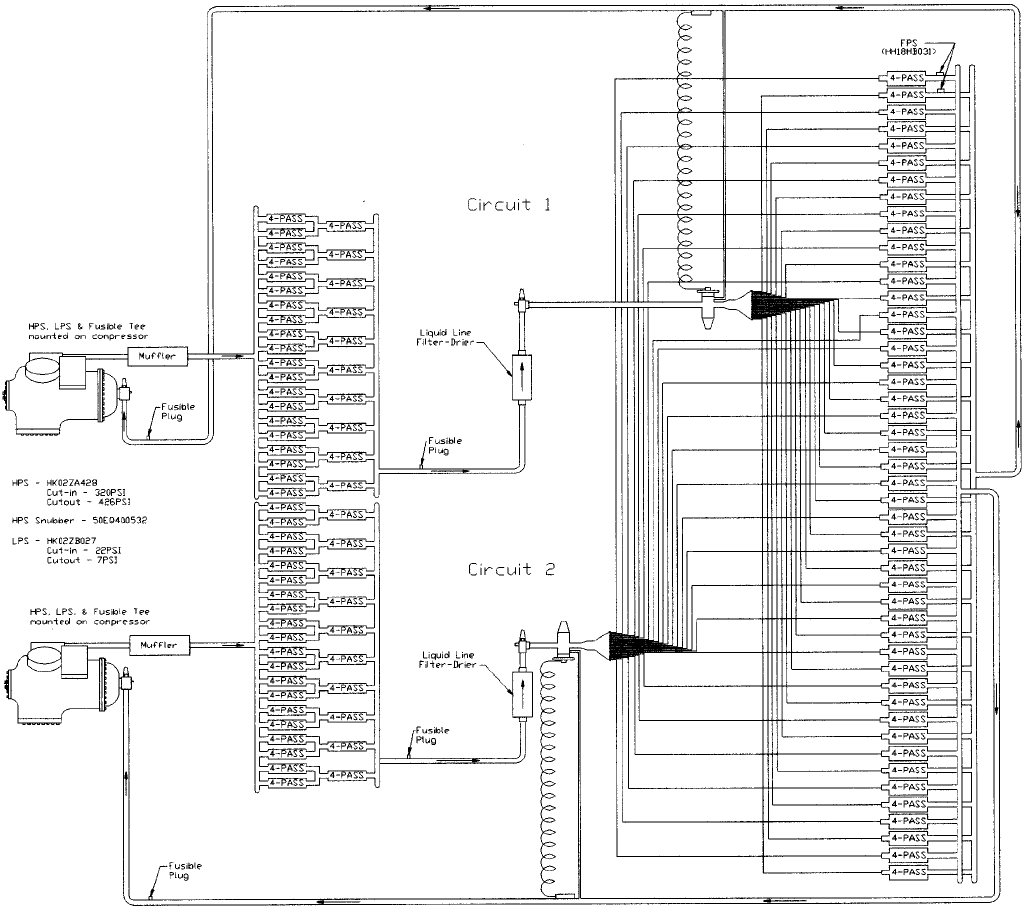
Typical refrigerant circuiting diagram is shown in Fig. 44.
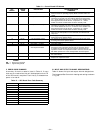
I. DIAGNOSTIC LEDs (Light-Emitting Diodes)
There are 3 LEDs (red, yellow, and green) on the lower right
hand side of the control board. The red light is used to check
unit operation and alarms. A constant pulse is normal unit
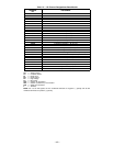
operation. A series of quick blinks indicates an alarm. Refer
to Table 12 for a description of alarms. The yellow and green
LEDs have no significance on 580G,H units.
LEGEND
FPS — Freeze Protection Switch
HPS — High-Pressure Switch
LPS — Low-Pressure Switch
Fig. 44 — Typical Refrigerant Circuiting
—33—