


4. Remove screws along bottom of damper assembly. Lo-
cate and mount blockoff baffle using these screws.
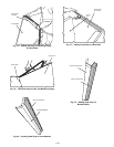
5. Assemble 2 filter tracks side-by-side with the as-
sembled ends together.
6.
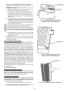
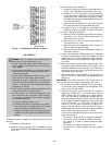
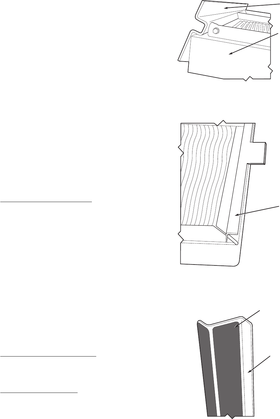
a. Attach mounting angle (without tabs) to the as-
sembled end of the filter track. See Fig. 23.
b. Attach 6 green clips (provided) to mounting angles.
Engagement section of clip faces inside of rack.
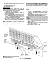
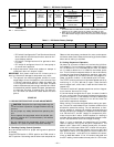
c. Attach remaining mounting angle (with tabs) to other
end of the filter track with no. 10 screws provided.
See Fig. 24.
7.
a. Place filter track assembly in bottom of hood by plac-
ing tabbed end into slotted side (with tab on bottom)
and attaching opposite end to hood with speed clips
and gasketed screws provided. Tabs can be hand bent
after inserted into the side.
NOTE: The filter track assembly end with screws should face
away from the other hood when mounted on the unit.
NOTE: Tabs from both filter tracks will be in the same space.
After one filter track has been inserted into board, bend the
tabs so they will not interfere with installation of the second
hood.
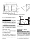
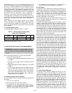
b. Attach black seal strip to filter cover. Seal strip should
be applied to flange (covering holes) and centerof large
flange. See Fig. 25.
8. Slide two 20 x 25-in. filters into cross members of hood
assembly.Attach filter cover over filters with screws and
speed clips provided.
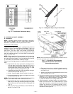
Minimum Damper Position Setting
Setting of the outdoor air damper position is performed in
conjunction with a shortened version of the field run test. This
is performed by first opening DIP switch no. 4 then no. 6.
The outdoor-air damper closes. The control allows 90 seconds
for the damper to close in case it is in the full open position.
Next, the indoor-fan contactor will energize. The outdoor air
damper will remain at 0% for 30 seconds. It will then move
to the 10% position for another 30 seconds. This will be
repeated at every 10% increment for 30 seconds until the
damper reaches 100% open. Close DIP switch no. 4 during
the 30 seconds immediately after the desired outdoor air mini-
mum damper position. The 30-second time period is to allow
time where DIP switch no. 4 can be closed. The default value
of the minimum outdoor air damper position is 20%. If the
desired minimum position is 30%, allow the damper posi-
tion to go to 10% for 30 seconds, then 20% for 30 seconds,
and when it reaches 30% close DIP switch no. 4 during the
30-second period following the 30% position.
The minimum outdoor air damper position is now set. Close
DIP switch no. 6.
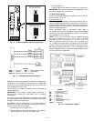
B. Economizer Settings
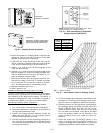
Accessory Enthalpy Control (Fig. 26)
The control (HH57AC077) is mounted in the economizer hood.
See Fig. 17. The enthalpy setting adjustment is on the en-
thalpy control. For maximum benefit of outdoor air, set en-
thalpy sensor control to A. See Fig. 27 and 28.
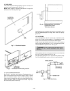
Enthalpy Control Installation
The outdoor air enthalpy control is installedon the inside panel
of the outdoor air hood.The enthalpy control should be mounted
when the outdoor air hoods are assembled. To install the con-
trol, perform the following procedure:
1. Turn off all power. Ensure disconnect is locked out.
2. Remove the economizer inlet filters from the bottom of
the right hand economizer hood. See Fig. 29.
MOUNTING ANGLE
(WITHOUT TABS)
FILTER TRACK
ASSEMBLY
Fig. 23 — Mounting Angle (Without Tabs)
Attached to Filter Track Assembly
MOUNTING ANGLE
(WITH TABS)
Fig. 24 — Mounting Angle (With Tabs)
Attached to Filter Track Assembly
BLACK SEAL STRIP
(CENTERED)
FILTER COVER
Fig. 25 — Attaching Seal Strip to Filter Cover
—16—