


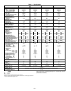
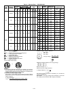
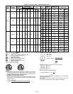
Table 2 — Evaporator Fan Motor Data
UNIT
SIZE
580G,H
MOTOR
HP
MOTOR
SHAFT
DIA.
(in.)
FAN
SHAFT
SPEED
(rpm)
MOTOR
SHEAVE
MOTOR
SHEAVE
PITCH
DIAMETER
(in.)
BUSHING
DIAMETER
(in.)
FAN
SHEAVE
FAN
SHEAVE
PITCH
DIAMETER
(in.)
BUSHING
DIAMETER
(in.)
BELT
(QUANTITY)
OUTSIDE
BELT
LENGTH
BELT
TENSION
(lb at
.24 in.)
240
5 1.12 717 BK55 4.8 None-1.125 1B5V124 12.4 B-1.9375 BX59 62 5.10
10 1.38 924 2BK50 4.4 None-1.375 2B5V86 8.6 B-1.9375 (2) BX51 54 5.21
15 1.62 1096 2B5V56 5.7 B-1.625 2B5V90 9.1 B-1.9375 (2) 5VX530 53 6.00
300
7.5 1.38 773 BK60H 5.4 H-1.375 1B5V124 12.4 B-1.9375 BX59 62 6.48
10 1.38 962 1B5V60 6.1 H-1.375 1B5V110 11.1 B-1.9375 5VX590 59 7.37
15 1.62 1106 2B5V54 5.5 B-1.625 2B5V86 8.7 B-1.9375 (2) 5VX530 53 6.12
324
10 1.38 848 2BK50 4.4 None-1.375 2B5V94 9.4 B-1.9375 (2) BX52 55 5.27
15 1.62 1059 2B5V48 4.9 B-1.625 2B5V80 8.1 B-1.9375 (2) 5VX500 50 6.63
20 1.62 1187 2B5V58 5.9 B-1.625 2B5V86 8.7 B-1.9375 (2) 5VX530 53 7.31
360
10 1.38 884 2BK50 4.4 H-1.375 2B5V90 9.0 B-1.9375 (2) BX51 54 5.24
15 1.62 1096 2B5V56 5.7 B-1.625 2B5V90 9.1 B-1.9375 (2) 5VX530 53 6.00
20 1.62 1187 2B5V58 5.9 B-1.625 2B5V86 8.7 B-1.9375 (2) 5VX530 53 7.31
NOTE: Motor shaft speed is 1750 rpm. The fan shaft diameter is 1
11
⁄
16
inches.
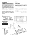
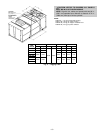
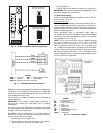
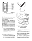
A. Positioning
Provide clearance around and above unit for airflow, safety,
and service access (Fig. 2 and 3).
Do not install unit in an indoor location. Do not locate air
inlets near exhaust vents or other sources of contaminated
air.
For proper unit operation, adequate combustion and ventila-
tion air must be provided in accordance with Section 5.3 (Air
for Combustion and Ventilation) ofthe National Fuel Gas Code,
ANSI Z223.1 (American National Standards Institute).
Although unit is weatherproof, guardagainst water from higher
level runoff and overhangs.
B. Roof Mount
Check building codes for weight distribution requirements.
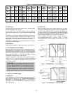
III. FIELD FABRICATE DUCTWORK
Secure all ducts to building structure. Use flexible duct con-
nectors between unit andducts as required. Insulate andweath-
erproof all external ductwork, joints, and roof openings with
counter flashing and masticin accordance with applicable codes.
Ducts passing through an unconditioned space must be
insulated and covered with a vapor barrier.
To attach ductwork to roof curb, insert ductwork approx-
imately 10 to 11 in. up into the curb. Connect ductwork to
14-gage roof curb material using sheet metal screws driven
from inside the duct.
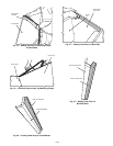
WARNING:
For vertical supply and return units, tools
or parts could drop into ductwork and cause an injury.
Install 90 degree elbow turns in the supply and return
ductwork between the unit and the conditioned space.
If a 90 degree elbow cannot be installed, then grilles of
sufficient strength and density should be installed to
prevent objects from falling into the conditioned space.
IV. UNIT DUCT CONNECTIONS
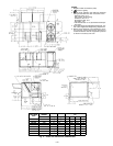
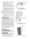
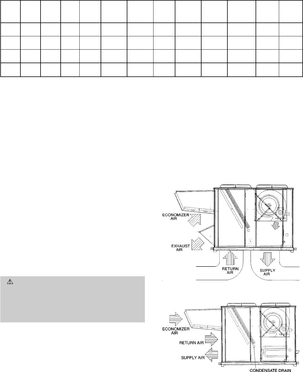
A. 580G Units
Unit is shipped for through-the-bottom duct connections. Duct-
work openings are shown in Fig. 2. Attach all ductwork to
roof curb. Air distribution is shown in Fig. 5. Refer to
installation instructions shipped with accessory roof curb for
more information.
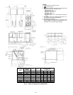
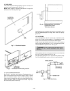
B. 580H Units
Remove shipping covers from supply and return air open-
ings.Attach field-supplied ductwork to unit. Use a single duct
over both return openings and a single duct over both sup-
ply openings. See Fig. 3 for duct opening dimensions. Secure
all ducts to the building structure. See Fig. 6. Use flexible
duct connectors between unit and ducts as required.
Install accessory barometric relief or power exhaust in
the field-fabricated return ductwork. Refer to Power
Exhaust/Barometric Relief Damper Hood section for more
information.
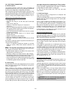
Fig. 5 — Air Distribution — Thru-the-Bottom
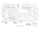
Fig. 6 — Air Distribution — Thru-the-Side
—7—