


controls up to 2 stages of power exhaust to maintain building
pressure. The power exhaust package can be configured to
deliver positive or negative building pressure. These power
exhaust stages are staged according to a percentage of the
economizer dampers position. Default values are 25% for
Stage 1 and 75% for Stage 2.
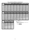
D. Smoke Control Modes
The 580G,H units with an optional expansion board perform
fire and smoke control modes. The expansion board provides
4 modes which can be used to control smoke within the con-
ditioned area. The modes of operation are fire shutdown, pres-
surization, evacuation, and smoke purge. See Table 7.
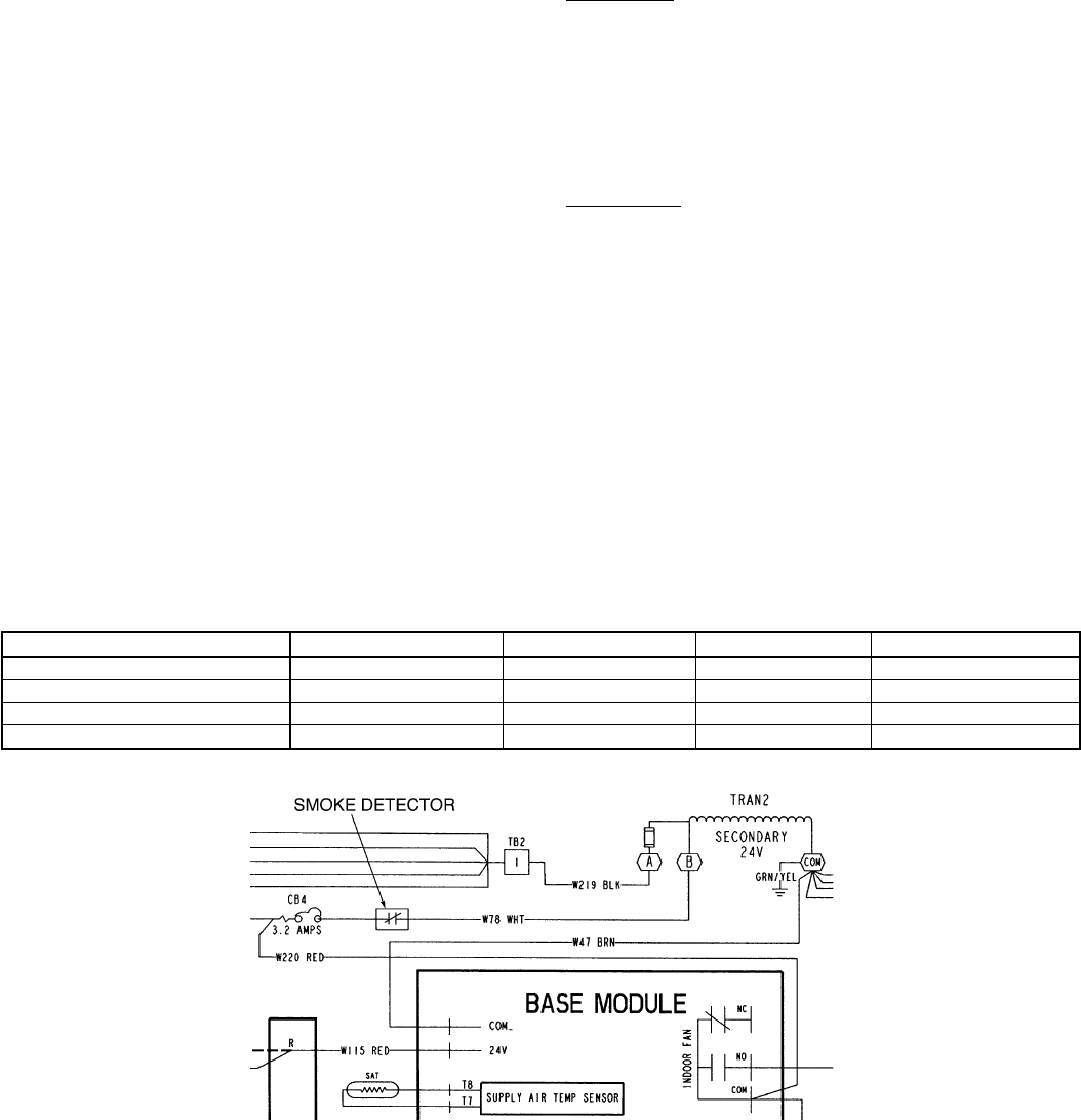
E. Smoke Detector
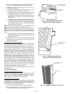
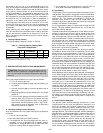
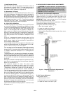
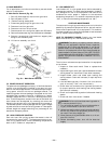
A smoke detector can be used to initiate fire shutdown. This
can be accomplished by a set of normally closed pilot relay
contacts which will interrupt power from the 24-v trans-
former, secondary ‘‘B’’ terminal to the control circuit breaker
(CB4). See Fig. 33. The wire that connects these two points is
white and labeled ‘‘W78.’’
NOTE: On standard gas models, the indoor fan will continue
to run 45 seconds after the call for heat has been terminated.
If fire shutdown is initiated the fan will stop immediately.
No 45-second delay will occur.
The smoke detector may be mounted in the return air duct
or the supply duct.
F. Indoor Air Quality Control
The accessory expansion board and accessory IAQ sensor are
required for IAQ control. The IAQ sensors operate with a
4 to 20 mA signal. The 4 to 20 mA signal is connected to
T11 (+) and T12 (−) on the expansion board for the IAQ sen-
sor, and T13 (+) and T14 (−) on the expansion board for the
OAQ (Outdoor Air Quality) sensor. The sensor is field-
mounted and wired to the expansion board installed in the
unit main control box. The IAQ sensor must be powered by a
field-supplied 24-v power supply (ungrounded). Do not use the
unit 24-v power supply to power the sensor.
Once installed, the sensor must be enabled. The sensor is con-
figured with default values which may be changed through
network access software. To work properly, the IAQ sensor
high and low reference points for the sensor that is used
must match the configured values. The expansion board
reacts toa4to20mAsignal from the IAQ sensor. The low
reference (4 mA output) must be configured to the minimum
IAQ sensor reading. The high reference (20 mA output) must
be configured to the maximum IAQ sensor reading.
The IAQ sensor can be configured to either low or high pri-
ority. The priority value can be changed by the user. The
default is low.
Low Priority
When the priority is set to low, the initial control is to the
IAQ set point, but the outside air damper position will change
to its minimum position when the space temperature is greater
than the occupied cooling set point plus 2° F or when the space
temperature is less than the occupied heating set point
minus 2° F. The damper will also change to minimum posi-
tion when the outdoor air quality is greater than the outdoor
air quality set point (ppm).
High Priority
When the priority is set to high, the IAQ set point controls
the outside air damper exclusively, with no regard to comfort
conditioning.
G. Time Guardா Circuit
The Time Guard function (built into the rooftop control board)
maintains a minimum off time of 5 minutes, a minimum on
time of 10 seconds, and a 10-second delay between compres-
sor starts.
H. Crankcase Heater
Unit main power supply must remain on to provide crank-
case heater operation. The crankcase heater in each compres-
sor keeps oil free of refrigerant while compressor is off.
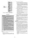
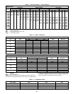
Table 7 — Smoke Control Modes
DEVICE PRESSURIZATION SMOKE PURGE EVACUATION FIRE SHUTDOWN
Economizer 100% 100% 100% 0%
Indoor Fan ON ON OFF OFF
Power Exhaust (all outputs) OFF ON ON OFF
Heat Stages OFF OFF OFF OFF
Fig. 33 — Field-Supplied Smoke Detector Wiring
—23—