


8. Use field-supplied wire ties to attach the violet wire to
the + terminal and the blue wire to the SR terminal.
9. Replace economizer filters.
10. Return power to unit.
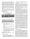
Disable Economizer
For applications where the economizer will not be used
(areas of high humidity), the economizer should be disabled.
To disable the economizer, perform the following:
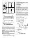
1. Turn off power. Lock out disconnect.
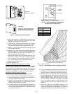
2. Locate the OAT (outdoor air thermistor) in the right hand
outdoor air damper area.
3. Locate the splice connecting the violet wire coming from
T24 on the base module board to the red wire coming
from T29 on the base module board. Remove the wire
nut and break the red to violet wire splice.
4. Cap off both wires. When the connection is broken, the
base module is fooled into thinking that the enthalpy is
not acceptable and economizer operation is disabled.
NOTE: Economizer operation can also be disabled by discon-
necting the OAT. This is not recommended due to the fact
that Unoccupied Free Cooling, IAQ Purge, and Low Ambient
Fan Cycle Control are also disabled. An OAT failure alarm
will also be issued.
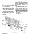
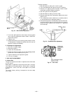
X. POWER EXHAUST/BAROMETRIC RELIEF DAMPERHOOD
All electrical connections have been made and adjusted at the
factory. Thepower exhaust blowers and barometric relief damp-
ers are shipped assembled and tilted back into the unit for
shipping. Brackets and extra screws are shipped in shrink
wrap around the dampers. If ordered, each unit will have
4 power exhaust blowers and motors or 4 barometric relief
dampers.
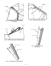
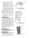
1. Remove 9 screws holding each damper assembly in place.
See Fig. 30. Each damper assembly is secured with
3 screws on each side and 3 screws along the bottom.
Save screws.
2. Pivot each damper assembly outward until edges of
damper assembly rest against inside wall of unit.
CAUTION:
Be careful when tilting blower assembly.
Hoods and blowers are heavy and can cause injury if
dropped.
3. Secure each damper assembly to unitwith 6 screws across
top (3 screws provided) and bottom (3 screws from
Step 1) of damper.
4. With screws saved from Step 1, install brackets on each
side of damper assembly.
5. Remove tape from damper blades.
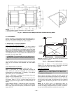
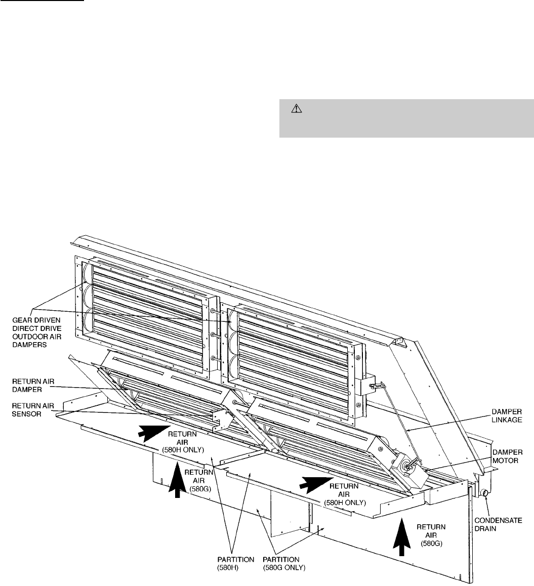
NOTE: Partitionsshown indicateboth sidesupply (580H)
and vertical supply (580G) units.
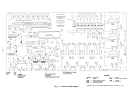
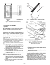
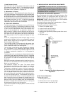
Fig. 29 — Economizer Details
—18—