


IX. OUTDOOR-AIR INLET ASSEMBLY
A. Economizer
NOTE: If accessory power exhaust or barometric relief pack-
ages are being added to the unit, install power exhaust or
barometric relief before installing economizer hoods.
Economizer Hood Assembly
The economizer hood is shipped in a package secured to the
outside of the unit and must be field assembled. There are
2 hoods on every unit. The 580H units are side supply and
side return. The return duct limits access to economizer
filters from below. Filter tracks (mounting angle without tabs)
must be installed correctly to allow access to economizer
filters from each side.
NOTE: Before assembly of the economizer hood, check along
the outer edges of the economizer assembly for any seal strip
protruding past the flanges. Trim the excess seal strip so that
it is flush with the economizer assembly flanges.
Perform the following procedure to assemble the economizer
hood:
1.
a. Apply black seal strip (provided in package) to out-
side top edge of hood sides. Wrap seal strip over to
cover top flange (4 hood sides). Make certain seal strip
covers screw holes. Allow strip to overhang
1
⁄
8
in. past
end opposite mounting flange. See Fig. 16.
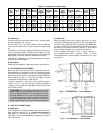
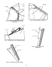
b. Assemble hood sides, top, and cross member with gas-
keted screws provided. See Fig. 17.
c. Attach 10 green speed clips (provided) to hood top.
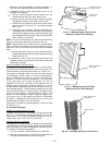
d. Apply black seal strip tomounting flanges (cover holes)
of hood sides. See Fig. 18.
NOTE: Each hood assembly has a slotted side that should be
adjacent to the other hood when mounted to the unit.
e. Apply black seal strip to hood top mounting flange.
Seal strip of hood top mounting flange must press
against seal strip of hood side mounting flanges. See
Fig. 19.
f. Add gray foam strip (provided) to cross members at
bottom tray. See Fig. 20.
g. Place gray foam strip on inside of slotted hood side
between filter and cross member opposite mounting
end. See Fig. 21.
h. Attach gray foam strip to blockoff baffle on outer face
area of flange. See Fig. 22.
2. Remove the screws on each end and along top of damper
assembly of unit. Remove top 2 screws on each side of
filter panel under damper assembly. Set hood assembly
in place and attach to unit using these screws.
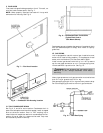
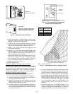
3. Attach accessory enthalpy bracket on hood side fur-
thest from control box end. Locate bracket on inside
upper right handcorner using hood mounting holes.Mount
outdoor-air thermistor to enthalpy bracket (if pur-
chased).Attach and wire enthalpy assembly. Place quick
connects on enthalpy wires.
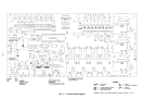
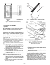
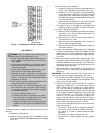
Fig. 15 — Field Control Thermostat Wiring
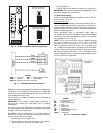
HOOD SIDE
TOP
FLANGE
SEAL
STRIP
BLACK
Fig. 16 — Adding Seal Strip to Top of Hood Sides
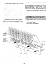
NOTE: Left side economizer hood has mounting anglewithout tabs and
filter track assembled end on opposite side.
Fig. 17 — Economizer Hood Assembly
(Right-Side Economizer Hood Shown)
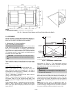
Exhaust Mounting Details
—14—