


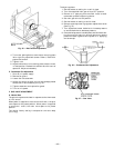

VII. FILTER DRIER
Replace whenever refrigerant system is exposed to
atmosphere.
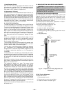
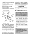
VIII. THERMOSTATIC EXPANSION VALVE (TXV)
Each circuit has one. It is nonadjustable and is factory set to
maintain 10 to 13° F superheat leaving the evaporator coil.
Controls flow of liquid refrigerant to the evaporator coils.
IX. PROTECTIVE DEVICES
A. Compressor Protection
Overcurrent
Each compressor has one manual reset, calibrated trip, mag-
netic circuit breaker. Do not bypass connections or increase
the size of the circuit breaker to correct trouble. Determine
the cause and correct it before resetting the breaker.
Overtemperature
Each 06D type compressor has an internal protector to pro-
tect it against excessively high discharge gas temperatures.
Crankcase Heater
Each compressor has a crankcase heater to prevent absorp-
tion of liquid refrigerant by oil in the crankcase when the com-
pressor is idle. Since power for the crankcase heaters is drawn
from the unit incoming power, main unit power must be on
for the heaters to be energized.
IMPORTANT: After a prolonged shutdown or service job,
energize the crankcase heaters for 24 hours before starting
the compressors.
B. Evaporator-Fan Motor Protection
A manual reset, calibrated trip, magnetic circuit breaker
protects against overcurrent. Do not bypass connections or
increase the size of the breaker to correct trouble. Determine
the cause and correct it before resetting the breaker. If the
evaporator-fan motor is replaced with a different horsepower
motor, resizing of the circuit breaker is required. Contact
Application Engineering.
C. Condenser-Fan Motor Protection
Each condenser-fan motor is internally protected against
overtemperature.
D. High- and Low-Pressure Switches
If either switch trips, or if the compressor overtemperature
switch activates, that refrigerant circuit will be automa-
tically locked out. To reset, manually move the thermostat
setting.
E. Freeze Protection Thermostat (FPT)
Freeze protection thermostats are located on the evaporator
coil for each circuit. One is located at the top and bottom of
each circuit. They detect frost build-up and turn off the com-
pressor, allowing the coil to clear. Once the frost has melted,
the compressor can be reenergized.
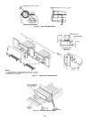
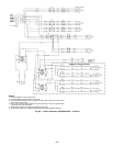
X. RELIEF DEVICES
All units have relief devices to protect against damage from
excessive pressures (i.e., fire). These devices are installed on
the suction line, liquid line, and on the compressor.
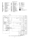
XI. CONTROL CIRCUITS
A. 24-V Circuit
This control circuit is protected against overcurrent by a
3.2-amp circuit breaker (CB4). Breaker can be reset. If it trips,
determine cause of trouble before resetting.
B. 115-V Circuit
This control circuit is protected against overcurrent by a
5.0-amp circuit breaker (CB3). Breaker can be reset. If it trips,
determine cause of trouble before resetting.
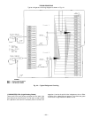
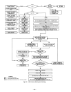
XII. COMPRESSOR LOCKOUT LOGIC
If any of the safeties trip, the circuit will automatically reset
(providing the safety has reset) and restart the compressor
in 15 minutes. If any of the safeties trip 3 times within a
90-minute period, then the circuit will be locked out and will
require manual resetting by turning off either the unit dis-
connect or the control circuit breaker.
XIII. REPLACEMENT PARTS
A complete list of replacement parts may be obtained from
any distributor upon request.
—32—