


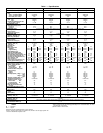
Operating voltage to compressor must be within voltage range
indicated on unit nameplate. On 3-phase units, voltages be-
tween phases must be balanced within 2% and the current
must be balanced within 10%.
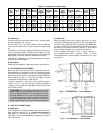
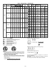
Use the formula in Table 3 to determine the percentage of
voltage imbalance.
IMPORTANT: If the supply voltage phase imbalance is
more than 2%, contact your local electric utility company
immediately.
Unit failure as a result of operation on improper line voltage
or excessive phase imbalance constitutes abuse and may cause
damage to electrical components.
On 208/230-v units, transformer no. 1 is wired for 230-v. If
208/230-v unit is to be run with 208-v power supply, the trans-
former must be rewired as follows:
1. Remove cap from red (208-v) wire.
2. Remove cap from spliced orange (230-v) wire. Discon-
nect orange wire from black unit power wire.
3. Cap orange wire.
4. Splice red wire and black unit power wire. Cap wires.
IMPORTANT: Be certain unused wires are capped. Failure to
do so may damage the transformers.
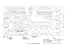
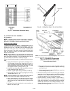
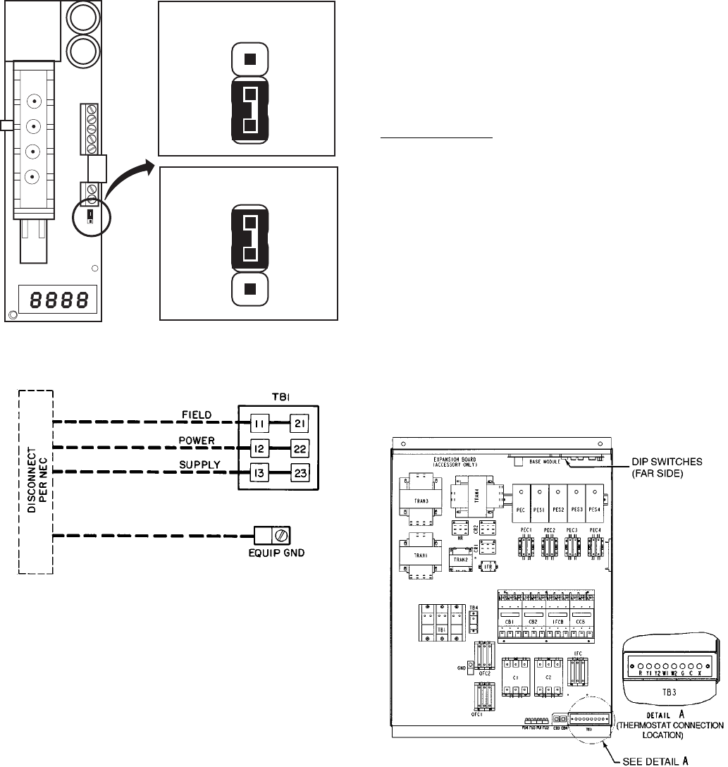
D. Field Control Wiring
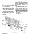
Install an approved accessory thermostat. Control box dia-
gram is shown in Fig. 14.
Thermostat Wiring
Install an approved accessory thermostat assembly (per cur-
rent price pages) according to the installation instructions in-
cluded with the accessory, or these instructions. Locate ther-
mostat assembly on a solid wall in the conditioned space to
sense average temperature.
Route thermostat cable or equivalent single leads of
no. 18 AWG (American Wire Gage) colored wire from subbase
terminals to low-voltage connections as shown on unit label
wiring diagram and in Fig. 15.
NOTE: For wire runs up to 50 ft, use no. 18 AWG insulated
wire (35 C minimum). For 50 to 75 ft, use no. 16 AWG
insulated wire (35 C minimum). For over 75 ft, use no. 14
AWG insulated wire (35 C minimum). All wire larger than
no. 18 AWG cannot be directly connected to the thermostat
and will require a junction box and splice at the thermostat.
Set heat anticipators settings to .1 for all voltages. Settings
may be changed slightly to provide a greater degree of com-
fort for a particular installation.
LEGEND
EQUIP — Equipment NEC — National Electrical Code
GND — Ground TB — Terminal Block
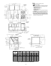
NOTE: TB1 Maximum wire size is 500 MCM.
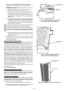
Fig. 13 — Field Power Wiring Connections
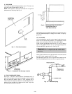
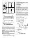
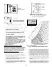
JUMPER CONNECTION
FOR VOLTAGE OUTPUT
JUMPER CONNECTION
FOR CURRENT OUTPUT
Fig. 12 — Indoor Air Quality Sensor Configuration
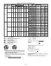
LEGEND
C—Compressor/Contactor
CB — Circuit Breaker
DIP — Dual In-Line Package
FU — Fuse
HR — Heater Relay
IF — Indoor Fan
OF — Outdoor Fan
PEC — Power Exhaust Controller
TB — Terminal Block
TRAN — Transformer
Fig. 14 — Control Box Diagram
—11—