


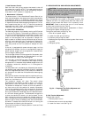
I. Head Pressure Control
Each unit has a fan cycling, outdoor thermostat to shut off
the outdoor-fan motor(s) at 55 F. The head pressure control
permits unit to operate with correct condensing tempera-
tures down to 35 F outdoor-air temperature.
J. Motormasterா III Control
The Motormaster III Solid-State Head Pressure Control is a
field-installed accessory fan speed control device actuated by
a temperature sensor. It is specifically designed for use on
Bryant equipment and controls the condenser-fan motor speed
in response to the saturated condensing temperature. For out-
door temperatures down to −20 F, it maintains condensing
temperature at 100 F. Refer to the accessory Motormaster
installation instructions for more information.
III. FIELD TEST OPERATION
The field test program is initiated by moving up DIP switch
no. 4 to the ‘‘On’’ position. The outdoor-air damper will close.
The control allows 90 seconds for the damper to close in case
it was in the full open position. Next, the indoor-fan con-
tactor will be energized, and the outside-air damper will
begin to open to its default value of 20% and stay at that po-
sition for a short period of time. The outdoor-air damper will
then open to its full open position and stay at that position
for a short period of time. The outdoor-air damper will then
close.
If the unit is equipped with power exhaust, stage 1 will be
energized for 5 seconds. If the unit is configured for stage 2 of
power exhaust, stage 2 will be energized for 5 seconds after
the first stage is deenergized.
The first stage of heat will be energized for 30 seconds, after
which the second stage heat will be energized for an addi-
tional 30 seconds. Heat is then deenergized.
The last step is the Cooling mode. Outdoor-fan contactor
no. 1 is energized. This is followed by each stage of cooling
energized with a 10-second delay between stages. After this
is complete, outdoor-fan contactor no. 2 is energized for
10 seconds.
The compressors will now deenergize, followed by the outdoor-
fan contactors and indoor-fan contactors. If the unit is equipped
with the Integrated Gas Control (IGC) board the indoor fan
will operate for an additional 30 seconds after deenergizing
the circuit.
Setting of the outdoor-air damper position is performed in con-
junction with a shortened version of the field test. Open DIP
switch no. 4 and then no. 6.
The outdoor-air damper will close. The control allows
90 seconds for the damper to close in case it is in the full
open position. Next, the indoor-fan contactor will energize.
The outdoor-air damper will remain at 0% for 30 seconds. It
will then move to the 10% position for another 30 seconds.
This will be repeated at every 10% increment for 30 seconds
until the damper reaches 100% open. Close DIP switch no. 4
during the 30 seconds immediately after the desired outdoor-
air minimum damper position. The 30-second time period is
to allow time where DIP switch no. 4 can be closed. The de-
fault value of the minimum outdoor-air damper position is
20%. If the desired minimum position is 30%, allow thedamper
position to go to 10% for 30 seconds, then 20% for 30 seconds,
and when it reaches 30% close DIP switch no. 4 during the
30-second period following the 30% position.
The minimum outdoor-air damper position is now set. Close
DIP switch no. 6.
IV. INDOOR AIRFLOW AND AIRFLOW ADJUSTMENTS
CAUTION:
For cooling operation, the recommended
airflow is 300 to 450 cfm per each 12,000 Btuh of rated
cooling capacity. For heating operation, the airflow must
produce a temperature rise that falls within the range
stamped on the unit rating plate.
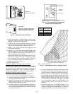
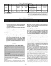
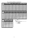
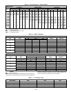
A. Evaporator Fan Performance Adjustment
Be sure evaporator fans rotate in the proper direction. See
Tables 8 and 9 for Fan Performance data. See Table 10 for
Motor Limitation data. See Table 11 for air quantity limits.
IMPORTANT: Check to ensure that the unit drive matches
the duct static pressure using Table 8.
Fan motor pulleys are factory set for speed shown in Table 1.
To change fan speeds, change pulleys.
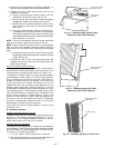
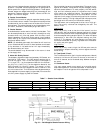
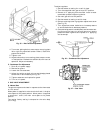
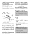
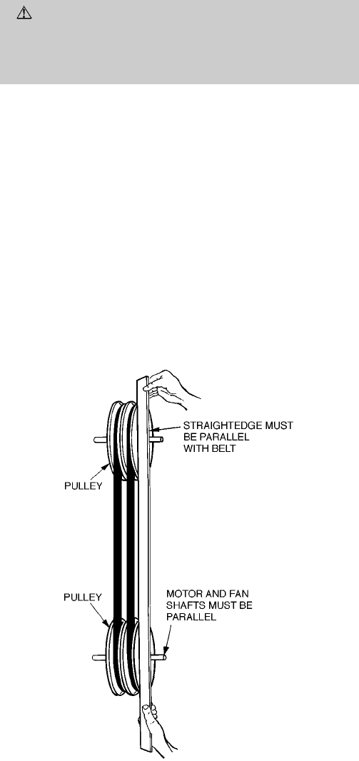
To align fan and motor pulleys (Fig. 34):
1. Shut off unit power supply.
2. Loosen fan shaft pulley bushing.
3. Slide fan pulley along fan shaft.
4. Make angular alignment by loosening motor from mount-
ing plate.
5. Retighten pulley.
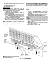
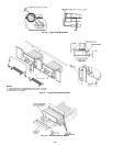
B. Belt Tension Adjustment
To adjust belt tension:
1. Remove power to unit.
2. Remove motor mount nuts and bolts.
3. Loosen fan motor nuts. See Fig. 35.
Fig. 34 — Evaporator-Fan Pulley Alignment and
Adjustment
—24—