


8
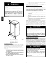
1/2 OD
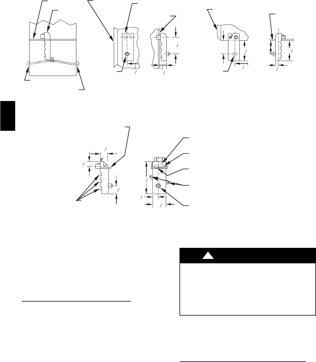
INDUCER HOUSING
DRAIN CONNECTION
1/4 OD
COLLECTOR BOX TO
TRAP RELIEF PORT
5/8 OD
COLLECTOR BOX
DRAIN CONNECTION
1/2 IN. PVC OR CPVC
SCREW HOLE FOR
UPFLOW OR DOWN-
FLOW APPLICATIONS
(OPTIONAL)
1
4
2
7
8
1
8
7
SLOT FOR SCREW
HORIZONTAL
APPLICATION
(OPTIONAL)
WIRE TIE
GUIDES
(WHEN USED)
1
2
1
3
4
1
3
4
FRONT VIEW SIDE VIEW
FURNACE
DOOR
FURNACE
DOOR
CONDENSATE
TRAP
7
8
1
4
26
4
FURNACE
SIDE
FURNACE
SIDE
1
2
1
1
4
26
4
3
4
5
3
4
5
4
SIDE VIEW FRONT VIEW END VIEW FRONT VIEW
3
4
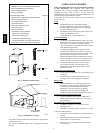
DOWNFLOW AND ALTERNATE
EXTERNAL UPFLOW APPLICATIONS
HORIZONTAL
APPLICATIONS
FIELD
DRAIN
CONN
FIELD
DRAIN
CONN
CONDENSATE
TRAP (INSIDE)
BLOWER SHELF
ALTERNATE DRAIN
TUBE LOCATION
UPFLOW APPLICATIONS
CONDENSATE TRAP
DRAIN TUBE LOCATION
(667mm) (38mm)
(124mm)
(667mm) (19mm)
(146mm) (146mm)
(57mm)
(3mm)
(181mm)
(44mm)
(88mm)
(19mm)
A07459
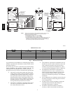
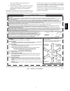
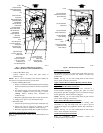
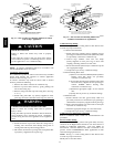
Fig. 6 -- Condensate Trap
NOTE: Failure to use CPVC elbows may allow drain to kink,
preventing draining.
k. Connect larger diameter drain t ube and clamp
(factory--supplied in loose parts bag) to condensate trap
and clamp securely.
l. Route tube to coupling and cut to appropriate length.
m. Attach tube to coupling and clamp securely.
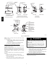
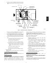
Condensate Trap (Alternate Upflow
Orientation)
An alternate location for the condensate trap is the left--hand side
of casing. (See Fig. 2 and 8.)
NOTE: If the alternate left--hand side of casing location is used,
the factory --connected drain and relief port tubes must be
disconnected and modified for attachment. See Condensate Trap
Tubing (Alternate Upflow Orientation) section for tubing
attachment.
To relocate condensate trap to the left--hand side, perform the
following:
1. Remove three tubes connected to condensate trap.
2. Remove trap from blower shelf by gently pushing tabs
inward and rotating trap.
3. Install casing hole filler cap (factory--supplied in loose
parts bag) into blower shelf hole where trap was removed.
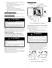
CARBON MONOXIDE POISONING HAZARD
Failure to follow this warning could result in personal
injury or death.
Casing hole filler cap must be installed in blower shelf
hole when condensate trap is relocated to prevent
combustion products being drawn in from appliances in
the equipment room.
!
WARNING
4. Install condensate trap into left-- hand casing hole by
inserting tube connection stubs through casing hole and
rotating until tabs snap into locking position.
5. Fill unused condensate trap casing holes with plastic filler
caps (factory--supplied in loose parts bag).
Condensate Trap Tubing (Alternate Upflow
Orientation)
NOTE: See Fig. 8 or tube routing label on main furnace door to
confirm location of these tubes.
355CAV