


4
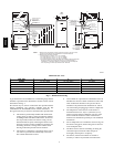
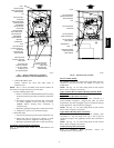
NOTES: 1. Minimum return-air openings at furnace, based on metal duct. If flex duct is used,
see flex duct manufacturer’s recommendations for equivalent diameters.
2. Minimum return-air opening at furnace:
a. For 800 CFM–16-in. round or 14
1
/2
x 12-in. rectangle.
b. For 1200 CFM–20-in. round or 14
1
/2
x 19
1
/2
-in. rectangle.
c. For 1600 CFM–22-in. round or 14
1
/2
x 23
1
/4
-in. rectangle.
d. For airflow requirements above 1800 CFM, see Air Delivery table in Product Data
literature for specific use of single side inlets. The use of both side inlets, a
combination of 1 side and the bottom, or the bottom only will ensure adequate
return air openings for airflow requirements above 1800 CFM.
17
5
⁄
16
"
24
1
⁄
2
"
27
9
⁄
16
"
TYP
27
5
⁄
8
"
29
11
⁄
16
"
TYP
30
13
⁄
16
"
32
5
⁄
8
"
TYP
33
1
⁄
4
"
TYP
CONDENSATE
DRAIN TRAP
LOCATION
(ALTERNATE
UPFLOW)
7
⁄8-IN. DIA
ACCESSORY
POWER ENTRY
7
⁄8-IN. DIA
POWER CONN
CONDENSATE DRAIN
TRAP LOCATION
(DOWNFLOW &
HORIZONTAL LEFT)
26
15
⁄
16
"
24
1
⁄
2
"
22
5
⁄
16
"
2-IN. COMBUSTION-
AIR CONN
1
⁄2-IN. DIA
GAS CONN
2-IN. VENT CONN
1
⁄2-IN. DIA THERMOSTAT
ENTRY
22
11
⁄
16
"
SIDE INLET
23
1
⁄
4
" TYP
SIDE INLET
1
1
⁄
4
"
1"
OUTLET
26
15
⁄
16
"
28
1
⁄
2
"
22
5
⁄
16
"
19"
13
⁄
16
"
5
⁄
8
"
5
⁄
16
"
1"
39
7
⁄
8
"
22
1
⁄
4
" TYP
11
⁄
16
"
7
⁄
16
"
24
3
⁄
16
"
BOTTOM INLET
18
1
⁄
4
"
22
11
⁄
16
"
2-IN. COMBUSTION-
AIR CONN
1
⁄2-IN. DIA
GAS CONN
7
⁄8-IN. DIA
POWER CONN
1
⁄2-IN. DIA
THERMOSTAT ENTRY
2-IN. VENT CONN
DIMPLE LOCATORS
FOR HORIZONTAL
HANGING
14
1
⁄
2
"
TYP
SIDE INLET
9
7
⁄
16
"
TYP
26
15
⁄
16
" TYP
CONDENSATE
DRAIN LOCATION
(UPFLOW)
30
1
⁄
2
"
9
⁄
16
"
TYP
CONDENSATE
DRAIN LOCATION
(UPFLOW)
E
INLET
11
/
16
"
11
/
16
"
D
13
/
16
"
13
/
16
"
OUTLET
A
AIRFLOW
26
1
⁄
4
"
26
1
⁄
4
"
CONDENSATE DRAIN
TRAP LOCATION
(DOWNFLOW &
HORIZONTAL RIGHT)
OR ALTERNATE
1
⁄
2
-IN. DIA GAS CONN
A05124
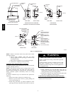
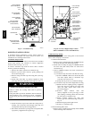
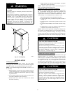
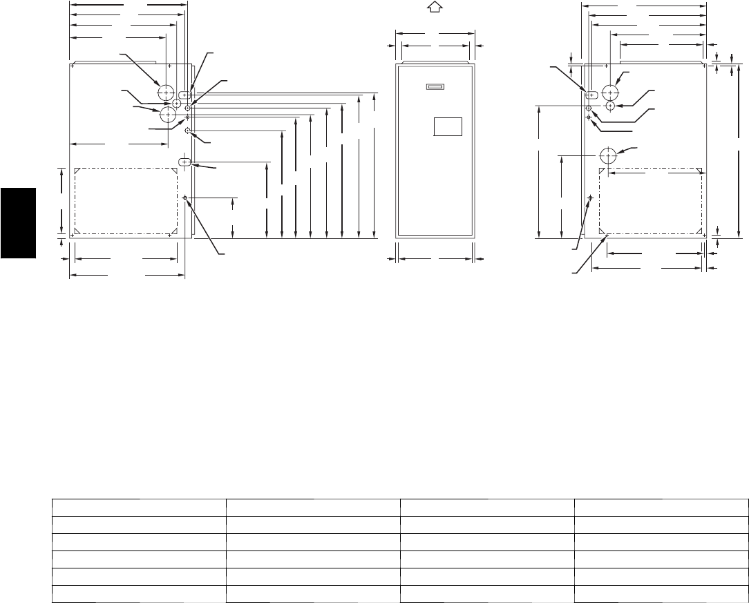
Dimensions (In. / mm)
UNIT SIZE A D E
042060 17---1/2 / 444.5 15---7/8 / 403.2 16 / 406.4
042080 21 / 533.4 19---3/8 / 492.1 19---1/2 / 495.3
060080 21 / 533.4 19---3/8 / 492.1 19---1/2 / 495.3
060100 21 / 533.4 19---3/8 / 492.1 19---1/2 / 495.3
060120 24---1/2 / 622.3 22---7/8 / 581.0 23 / 584.2
Fig. 2 -- Dimensional Drawing
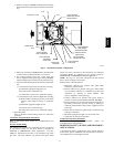
A gas--fired furnace for installation in a residential garage must be
installed as specified in the Hazardous Locations section of these
instructions and Fig. 5.
The furnace may be used for construction heat provided that the
furnace installation and operation complies with the first
CAUTION in the LOCATION section of these instructions.
This gas furnace may be used for construction heat provided that:
S The furnace is permanently installed with all electrical
wiring, piping, air filters, venting and ducting installed
according to these installation instructions. A return air
duct is provided, sealed to the furnace casing, and ter-
minated outside the s pace containing the furnace. This
prevents a negative pressure condition as created by the
circulating air blower, causing a flame rollout and/or
drawing combustion products into the structure.
S The furnace is controlled by a thermostat. It may not be
“hot wired” to provide heat continuously to the struc-
ture without thermostatic control.
S Clean outside air is provided for combustion. This is to
minimize the corrosive effects of a dhesives, sealers and
other construction materials. It also prevents the en-
trainment of drywall dust into combustion air, which
can cause fouling and plugging of furnace components.
S The temperature of the return air to the furnace is
maintained between 55_F(13_C) and 80_F(27_C),
with no evening setback or shutdown. The use of the
furnace while the structure is under construction is
deemed to be intermittent operation per our installation
instructions.
S The air temperature rise is within the rated rise range on
the furnace rating plate, and the firing rate has been set
to the nameplate value.
S The filters used to clean the circulating air during the
construction process must be either changed or
thoroughly cleaned prior to occupancy.
S The furnace, ductwork and filters are cleaned as
necessary to remove drywall dust and construction
355CAV