


59
NOTE: When using an electronic thermostat, set cycle rate for 3
cycles per hr .
3. Return setup switch SW1--2 to OFF position and replace
thermostat on subbase.
Check Safety Contr
ols
This section covers the safety controls that must be checked
before the installation is complete. The flame sensor, gas valve,
and pressure switches were all checked in the Start--up procedure
section as part of normal operation.
Check Primary Limit Contr
ol
This control shuts off the gas control system and energizes the
air--circulating blower motor if furnace overheats.
1. The recommended method of checking this limit control is
to gradually block off return air after furnace has been op-
erating for a period of at least 5 minutes.
2. As soon as limit control has shut off burners, a status code
33 will appear on furnace control.
3. The return--air opening should be unblocked to permit
normal air circulation.
By using this method to check the limit control, it can be
established that the limit is functioning properly and the furnace
will operate safely if there is a restricted return--air duct or motor
failure. If the limit control does not function during this test, the
cause must be determined and corrected.
Check Pressure
Switches
This control proves operation of the draft inducer. Check switch
operation as follows:
1. Turn off 115--v power to furnace.
2. Remove control access door and disconnect inducer motor
12--pin wire harness at inducer motor.
3. Turn on 115--v power to furnace.
4. Set thermostat t o “call for heat.” When pressure switches
are functioning properly, status code 42 will flash on fur-
nace control approximately 20 sec after thermostat switch
is closed. If either a status code 31 or 32 is flashed when
inducer motor i s disconnected, the furnace will shut itself
down immediately. Determine the reason pressure
switches did not function properly and correct the condi-
tion.
5. Turn off 115--v power to furnace.
6. Reconnect inducer motor wire harness. Reinstall furnace
access door.
7. Turn on 115--v power to furnace.
8. Reset thermostat to desired temperature.
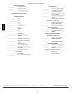
CHECKLIST
1. Put away tools and instruments. Clean up debris.
2. Verify flame rollout manual reset switch has continuity.
3. Verify that blower and main access doors are properly
installed.
4. Cycle test furnace with room thermostat.
5. Check operation of accessories per manufacturer’s instruc-
tions.
6. Review User’s Manual with owner.
7. Leave literature packet near
furnace.
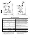
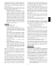
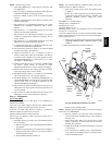
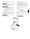
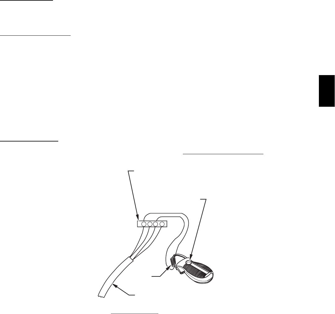
R Y W G
10 TURNS
THERMOSTAT SUBBASE
TERMINALS WITH
THERMOSTAT REMOVED
(ANITICIPATOR, CLOCK, ETC.,
MUST BE OUT OF CIRCUIT.)
HOOK-AROUND
AMMETER
EXAMPLE:
5.0 AMPS ON AMMETER
10 TURNS AROUND JAWS
=
0.5 AMPS FOR THERMOSTAT
ANTICIPATOR SETTING
FROM UNIT 24-V
CONTROL TERMINALS
A96316
Fig. 63 -- Amp Draw with Ammeter
355CAV