


49
The wall thermostat ”calls for heat”, closing t he R to W1 circuit
for medium--heat or closing the R to W1--and--W2 circuits for
high--heat. The furnace control performs a self--check, and
verifies the low--heat and medium--heat pressure switch c ontacts
LPS and MPS are open, then de--energizes the HPSR relay to
close the NC contact.
The start up and shut down functions and delays described above
apply to the 2--stage medium/high heating mode as well, except
for switching from high-- to medium--heat.
1. Switching from High-- to Medium--Heat —Ifthe
thermostat R to W2 circuit opens, and the R to W 1 circuit
remains closed, the furnace control CPU will gradually
decrease the inducer motor speed to the required
medium--heat RPM. When the inducer motor IDM
reduces pressure sufficiently, the highheat pressure switch
HPS will open and the high--heat gas valve solenoid
GV--HI will be de--energized. The gas valve solenoid
GV--M will remain energized as long as the low--heat
pressure switch LPS remains closed. When the inducer
motor speed gets within 15% of the required medium--heat
RPM the furnace control CPU will start a 5 second blower
airflow change delay. After the 5 second blower airflow
change delay is completed the blower airflow will
transition to medium--heat airflow.
Cooling
Mode
The thermostat “calls for cooling.”
2. Single--Speed Cooling
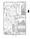
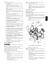
See Fig. 29 for thermostat connections.
The thermostat closes the R to G--and--Y circuits. The R to
Y circuit starts the outdoor unit, and the R to G --and--Y/Y2
circuits start the furnace blower motor BLWM on cooling
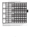
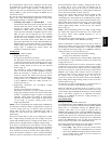
airflow. Cooling airflow is based on the A/C selection
shown in Fig. 47.
The electronic air cleaner terminal EAC--1 is energized
with 115 vac when the blower motor BL WM is operating.
When the thermostat is satisfied, the R to G--and--Y
circuits are opened. The outdoor unit will stop, and the
furnace blower motor BLWM will continue operating at
cooling airflow for an additional 90 seconds. Jumper
Y/Y2 to DHUM to redu ce the cooling off--delay to 5
seconds. (See Fig. 33.)
3. Single--Stage Thermostat and Two--Speed Cooling
(Adaptive Mode)
See Fig. 59 for thermostat connections.
This furnace can operate a two--speed cooling unit with a
single--stage thermostat because the furnace control CPU
includes a programmed adaptive sequence of controlled
operation, which selects low--cooling or high--cooling
operation. This selection is based upon the stored history
of the length of previous cooling period of the
single-- stage thermostat.
NOTE: The air conditioning relay disable jumper ACRDJ must
be connected to enable the adaptive cooling mode in response to
a call for cooling. (See Fig. 33.) When in place the furnace
control CPU can turn on the air conditioning relay ACR to
energize the Y/Y2 terminal and switch the outdoor unit to
high--cooling.
The furnace control CPU can start up the cooling unit in either
low-- or high--cooling. If starting up in low--cooling, the furnace
control CPU determines the low--cooling on--time (from 0 to 20
minutes) which is permitted before switching to high--cooling.
If the power is interrupted, the stored history is erased and the
furnace control CPU will select low--cooling for up to 20 minutes
and then energize the air conditioning relay ACR to energize the
Y/Y2 terminal and switch the outdoor unit to high--cooling, as
long as the thermostat continues to call for cooling. Subsequent
selection is based on stored history of the thermostat cycle times.
The wall thermostat “calls for cooling”, closing the R to G and--
Y circuits. The R to Y1 circuit starts the outdoor unit on
low--cooling speed, and the R to G--and--Y1 circuits starts the
furnace blower motor BLWM at low--cooling airflow which is the
true on--board CF selection as shown in Fig. 47.
If the furnace control CPU switches from low --cooling to high
cooling, the furnace control CPU will energize the air
conditioning relay ACR. When the air conditioning relay ACR is
energized the R to Y1--and--Y2 circuits switch the outdoor unit to
high--cooling speed, and the R to G--and--Y1-- and--Y/Y2 circuits
transition the furnace blower motor BLWM to high--cooling
airflow. High--cooling airflow is based on the A/C selection
shown in Fig. 47.
NOTE: When transitioning from low--cooling to high--cooling
the outdoor unit compressor will shut down for 1 minute while
the furnace blower motor BLWM transitions to run at
high--cooling airflow.
The electronic air cleaner terminal EAC--1 is ener gized with 115
vac whenever the blower motor BLWM is operating.
When the thermostat is satisfied, t he R to G--and--Y circuit a re
opened. The outdoor unit stops, and the furnace blower BLWM
and electronic air cleaner terminal EAC--1 will remain energized
for an additional 90 seconds. Jumper Y1 to DHUM to reduce the
cooling off-- delay to 5 seconds. (See Fig. 33.)
4. Two--Stage Thermostat and Two--Speed Cooling
See Fig. 58 for thermostat connections.
NOTE: The air conditioning relay disable jumper ACRDJ must
be disconnected to allow thermostat control of the outdoor unit
staging. (See Fig. 33.)
The t hermostat closes t he R to G--and--Y1 circuits for low cooling
or closes the R to G--and--Y1--and--Y2 circuits for high cooling.
The R to Y1 circuit starts the outdoor unit on low cooling speed,
and the R to G--and--Y1 circuit starts the furnace blower motor
BLWM at low--cooling airflow which is the true on--board CF
selection as shown in Fig. 47. The R to Y1--and--Y2 circuits start
the outdoor unit on high --cooling speed, and the R to
G--and--Y/Y2 circuits start the furnace blower motor BLWM at
high--cooling airflow. High--cooling airflow is based on the A/C
selectionshowninFig.47.
The electronic air cleaner terminal EAC--1 is ener gized with 115
vac whenever the blower motor BLWM is operating.
When the thermostat is satisfied, the R to G--and--Y1 or R to
G--and--Y1 --and--Y2 circuits are opened. The outdoor unit stops,
and the furnace blower BLWM and electronic air cleaner terminal
EAC--1 will remain energized for an additional 90 seconds.
Jumper Y1 to DHUM to reduce the cooling off--delay to 5
seconds. (See Fig. 33.)
Thermidistat
Mode
See Fig. 52--55 for thermostat connections.
The dehumidification output, DHUM on the Thermidistat should
be connected to th e furnace control thermostat terminal DHUM.
When there is a dehumidify demand, the DHUM input is
activated, which means 24 vac signal is r emoved from the
DHUM input terminal. In other words, the DHUM input logic is
reversed. The DHUM input is turned ON when no dehumidify
demand exists. Once 24 vac is detected by the furnace control on
the DHUM input, the furnace control operates in Thermidistat
mode. If the DHUM input is low for more than 48 hours, the
furnace control reverts back to non--Thermidistat mode.
The cooling operation described above also applies to operation
with a Thermidistat. The exceptions are listed below:
1. Low cooling – When the R to G--and--Y1 circuit is closed
and there is a demand for dehumidification, the furnace
blower motor BLWM will drop the blower airflow to 86%
of low cooling airflow which is the true on --board CF
selectionasshowninFig.47.
355CAV