


21
FILTER
RETAINE
R
WASHABLE
FILTER
A93045
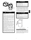
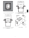
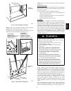
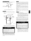
Fig. 24 -- Filter Installed for Side Inlet
NOTE: Side return--air openings can ONLY be used in Upflow
configurations. Install filter(s) as shown in Fig. 24.
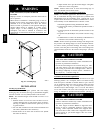
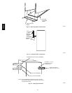
For bottom return--air applications, filter may need to be cut to fit
some furnace widths. Install filter as shown in Fig. 25.
WASHABLE
FILTER
FILTER
SUPPORT
FILTER
RETAINER
17
1
⁄
2
-IN. WIDE
CASINGS ONLY:
INSTALL FIELD-SUPPLIED
FILTER FILLER STRIP
UNDER FILTER.
1
″
24
1
/
2
″
3″
21-IN. WIDE
CASINGS ONLY:
SUPPORT RODS (3)
EXTEND 1/4" ON EACH
SIDE OF FILTER AND
REST ON CASING FLANGE
A00290
Fig. 25 -- Bottom Filter Arrangement
NOTE: Remove and discard bottom closure panel when bottom
inlet is used.
Bottom Closure
Panel
These furnaces are shipped with bottom closure panel installed in
bottom return --air opening. This panel MUST be in place when
side return air is used.
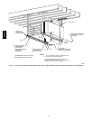
To remove bottom closure panel, perform following:
1. Tilt or raise furnace and remove two screws holding front
filler panel. (See Fig. 26.)
2. Rotate front filler panel downward to release holding tabs.
3. Remove bottom closure panel.
4. Reinstall front filler panel and screws.
Gas
Piping
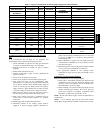
Gas piping must be installed in accordance with national and
local codes. Refer to NFGC in the U.S. Canadian installations
must be made in accordance with CAN/CSA--B149.1--05 and all
authorities having jurisdiction. Gas supply line should be a
separate line running directly from meter to furnace, if possible.
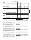
Refer to Table 3 for recommended gas pipe sizing. Risers must be
used to connect to furnace and to meter. Support all gas piping
with appropriate straps, hangers, etc. Use a minimum of one
hanger every 6 ft. Joint compound (pipe dope) should be applied
sparingly and only to male threads o f joints. Pipe dope must be
resistant to propane gas.
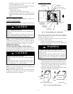
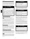
FIRE OR EXPLOSION HAZARD
Failure to follow this warning could result in personal
injury, death, or property damage.
-- Connect gas pipe to furnace using a backup wrench to
avoid damaging gas controls.
-- Gas valve shutoff switch MUST be facing forward or
tilted upward.
-- Never purge a gas line into a combustion chamber.
Never test for gas leaks with an open flame. Use a
commercially available s oap solution made s pecifically
for the detection of l eaks to check all connections.
-- Use proper length of pipe to avoid stress on gas
control manifold.
-- If a flexible connector is required or allowed by
authority having jurisdiction, black iron pipe shall be
installed at furnace gas valve and extend a minimum
of 2 in. (50.8mm) outside furnace casing.
--Protect gas valve from water and debris. Gas valve
inlet and/or inlet piping must remain capped until gas
supply line is permanently installed to protect the valve
from moisture and debris. Also, install a sediment trap
in the gas supply piping at the inlet to the gas valve.
!
WARNING
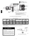
Install a sediment trap in riser leading to furnace. Trap can be
installed by connecting a tee to riser leading to furnace so
straight--through section of tee is vertical. Then connect a capped
nipple into lower end of tee. Capped nipple should extend below
level of gas controls. Place a ground joint union between gas
control manifold and manual gas shutoff valve. (See Fig. 27.)
An accessible manual shutoff valve MUST be installed external
to furnace casing and within 6 ft (1.8 m)of furnace. A 1/8--in.
NPT (3.2mm) plugged tapping, accessible for test gauge
connection, MUST be installed immediately upstream of gas
supply connection to furnace and downstream of manual shutoff
valve.
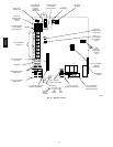
Gas line grommet (factory--supplied loose parts bag) should be
used when installing gas piping. Gas line e ntry hole filler plug
should be installed in unused gas line entry hole. (See Fig. 28.)
355CAV