


13
1. Disconnect collector box pressure tube (pink label)
attached to High Pressure Switch.
2. Use smaller diameter tube (factory--suppled in loose pars
bag) to extend tube disconnected in Item 1.
3. Route extended tube:
a. Behind inducer housing.
b. Between blower shelf and inducer housing.
4. Determine appropriate lenght, cut, and reconnect tube to
High Pressure Switch connections labeled COLLECTOR
BOX.
Condensate Trap Freeze Pr
otection
Refer to Condensate Drain Protection section for
recommendations and procedures.
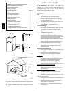
Construct a Working
Platform
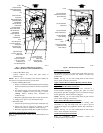
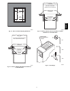
Construct working platform where all required furnace clearances
are met. (See Fig. 3 and 12 or 13.)
UNIT OPERATION HAZARD
Failure to follow this caution may result in intermittent unit
operation.
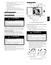
The condensate trap MUST be installed below furnace. See
Fig. 6 for dimensions. The drain connection to condensate
trap must also be properly sloped to an open drain.
CAUTION
!
NOTE: A 12--in. (304.8mm) minimum offset pipe section is
recommended with short (5 to 8 ft or 1.5 M to 2.4 M) vent
systems. This recommendation is to reduce excessive condensate
droplets from exiting the vent pipe. (See Fig. 12, 13, or 44.)
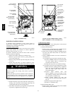
HORIZONTAL RIGHT
(SUPPLY--AIR DISCHARGE) APPLICATIONS
A horizontal right furnace application is where furnace blower is
located to the left of combustion and controls section of furnace,
and conditioned air is discharged to the right.
PROPERTY DAMAGE HAZARD
Failure to follow this caution may result in property
damage.
Local codes may require a drain pan under entire furnace
and condensate trap when a condensing furnace is used in
an attic application or over a finished ceiling.
CAUTION
!
NOTE: In Canada, installations shall be in accordance with
current NSCNGPIC and/or local codes.
NOTE: The auxiliary junction box (J--box ) MUST be r elocated
to opposite side of furnace casing. (See Fig. 14.) See Electrical
Connection section for J-- box relocation.
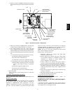
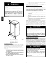
Condensate Trap
Location
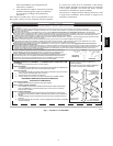
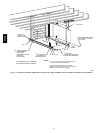
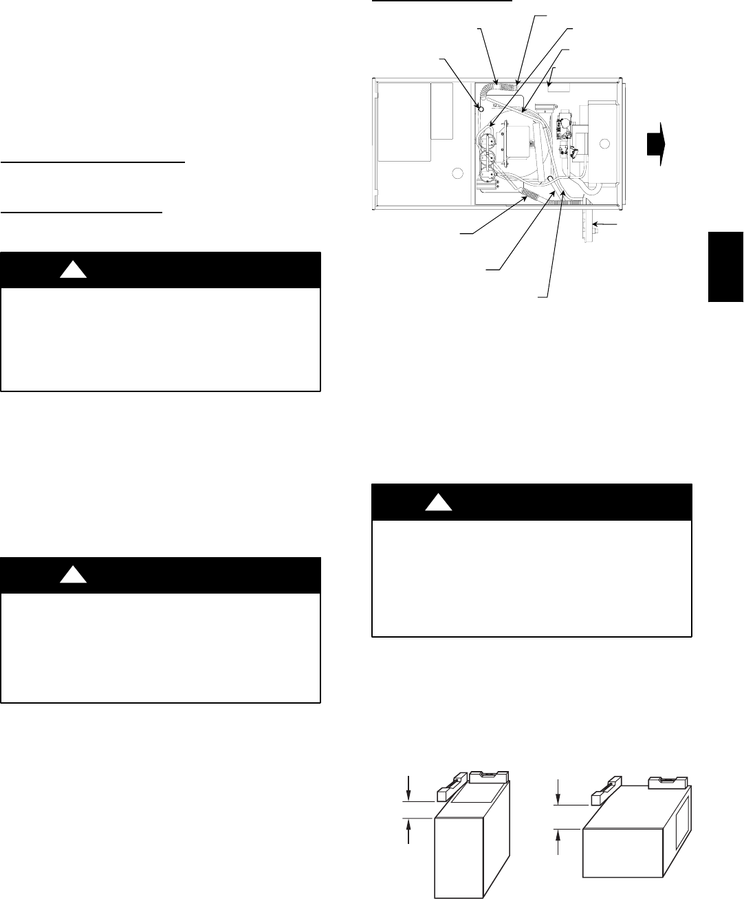
CAP
PLUG
COLLECTOR BOX
DRAIN TUBE (BLUE &
WHITE STRIPED)
INDUCER HOUSING
(MOLDED) DRAIN
TUBE (VIOLET)
COLLECTOR BOX TUBE (PINK)
COLLECTOR BOX
DRAIN TUBE (BLUE)
COLLECTOR BOX
EXTENSION TUBE
CONDENSATE
TRAP
COLLECTOR BOX
TUBE (GREEN)
AUXILIARY “J” BOX RELOCATED HERE
A07279
Fig. 14 -- Horizontal Right Tube Configuration
The condensate trap must be removed from the factory--installed
blower shelf location and relocated in selected application
location as shown in Fig. 2 or 14.
To relocate condensate trap from the blower shelf to desired
location, perform the following:
1. Remove three tubes connected to condensate trap.
2. Remove trap from blower shelf by gently pushing tabs
inward and rotaing trap.
CARBON MONOXIDE POISONING HAZARD
Failure to follow this warning could result in personal
injury or death.
Casing hole filler cap must be installed in blower shelf hole
when condensate trap is relocated to prevent combustion
products being drawn in from appliances in the equipment
room.
!
WARNING
3. Install casing hole filler cap (factory--supplied in loose
parts bag) into blower shelf hole where trap was removed.
4. Install condensate trap into right--hand side casing hole by
inserting tube connection stubs through casing hole an
rotating until tabls snap into locking position.
5. Fill unused condensate trap casing holes with plastic filler
caps (factory--supplied in loose parts bag).
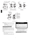
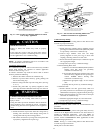
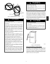
UPFLOW OR DOWNFLOW HORIZONTAL
FRONT
LEVEL (0″)
TO
1
⁄2″ MAX
MIN
1
⁄4″
TO
1
⁄2″ MAX
FRONT
A02146
Fig. 15 -- Proper Condensate Drainage
355CAV