


25
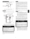
Factory Installed J--Box
Location
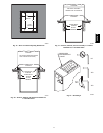
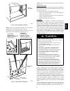
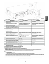
Install power entry hole filler plugs (factory--supplied in loose
parts bag) in unused power entry holes. (See Fig. 31.)
A05113
FACTORY
INSTALLED
LOCATION
UNUSED 7/8-IN.
DIAMETER POWER
ENTRY HOLES
POWER ENTRY HOLE
FILLER PLUG (FACTORY-
SUPPLIED LOOSE PARTS BAG)
A05113
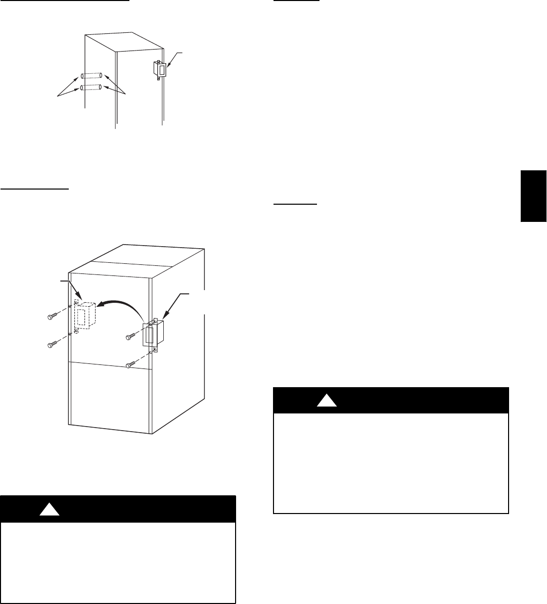
Fig. 31 -- Factory Installed J--Box Location
J--Box
Relocation
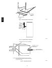
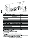
1. Remove two screws holding auxiliary J--box. (See Fig.
32.)
2. Rotate J--box 180_ and attach box to left side, using holes
provided.
FACTORY
INSTALLED
LOCATION
ALTERNATE
FIELD
LOCATION
A00212
Fig. 32 -- J--Box Relocation
3. Install power entry hole f iller plugs (factory--supplied
loose parts bag) in unused power entry holes. (See Fig.
31.)
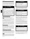
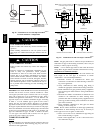
FIRE OR ELECTRICAL SHOCK HAZARD
Failure to follow this warning could result in personal
injury, death, or property damage.
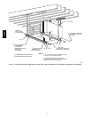
If manual disconnect switch is to be mounted on furnace,
select a location where a drill or fastener will not contact
electrical or gas components.
!
WARNING
NOTE: If modulating dampers are used, blower motor
automatically compensates for modulating dampers. If manual
disconnect switch is to be mounted on furnace, select a location
where a drill or fastener will not contact electrical or gas
components.
24--v
wiring
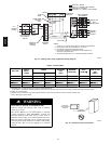
Make field 24--v thermostat connections at 24--v terminal block
on furnace control. Y wire from thermostat MUST be connected
to Y/Y2 terminal on control, as shown in Fig. 19, for proper
cooling operation. The 24--v terminal block is marked for easy
connection of field wiring. (See Fig. 33.) The 24--v circuit
contains a 3--amp, automotive--type fuse located on furnace
control. (See Fig. 33.)
Any electrical shorts of 24--v wiring during installation, service,
or maintenance may cause fuse to blow. If fuse replacement is
required, use only a fuse of identical size (3 amp) and type. The
furnace control will flash status code 24 when fuse needs
replacement.
NOTE: Use AWG No. 18 color--coded copper thermostat wire
for lengths up to 100 ft. For wire lengths over 100 ft, use AWG
No. 16 wire.
NOTE: For additional thermostat connection diagrams,
reference Fig. 52--59.
Accessories
1. Electronic Air Cleaner (EAC)
The furnace control EAC terminals are energized with
115v (1.0--amp maximum) during blower operation.
Connect an accessory Electronic Air Cleaner (if used)
using 1/4--in. female quick connect terminals to the two
male 1/4--in. quick--connect terminals on the control board
marked EAC--1 and EAC--2. The terminals are rated for
115VAC, 1.0 amps maximum and are energized during
blower motor operation. (See Fig. 33.)
NOTE: Low stage airflow may slightly increase the trace
amount of ozone created by an electronic air cleaner. Individual
sensitivity levels to ozone, along with other operating
characteristics of electronic air cleaners may affect the amount
noticed by an individual. Refer to the air cleaner manufacturer’s
installation instructions for more information regarding ozone
and ozone reduction methods available for your air cleaner.
UNIT DAMAGE HAZARD
Failure to follow this caution may result in unit component
damage.
DO NOT connect furnace control HUM terminal to HUM
(humidifier) terminal on Thermidistatt, Zone Controller or
similar device. See Thermidistatt, Zone Controller,
thermostat, or c ontroller manufacturer’ s instructions for
proper connection.
CAUTION
!
2. Humidifier (HUM)
Connect an accessory 24 VAC, 0.5 amp maximum
humidifier (if used) to the 1/4 --in. male quick--connect
HUM terminal and COM --24V screw terminal on the
control board thermostat strip. The HUM terminal is
energized when blower is energized in heating. (See Fig.
33.)
355CAV