


53
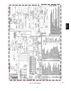
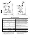
NOTE: Reference Fig. 52--59:
1. Heat pump MUST have a high pressure switch for dual
fuel applications.
2. Refer to outdoor equipment Installation Instructions for
additional information and setup procedure.
3. Select the “ZONE” position on the two--speed heat pump
control.
4. Outdoor Air Temperature Sensor must be attached in all
dual fuel applications.
5. Dip switch No.1 on Thermidistat should be set in OFF
position for air conditioner installations. This is factory
default.
6. Dip switch No. 1 on Thermidistat should be set in ON
position for heat pump installations.
7. Dip switch No. 2 on Thermidistat should be set in OFF
position for single--speed compressor operation. This is
factory default.
8. Dip switch No. 2 on Thermidistat should be set in ON
position for two--speed compressor operation.
9. Configuration Option No. 10 “Dual Fuel Selection” must
be turned ON in all dual fuel applications.
10. NO connection should be made to the furnace HUM
terminal when using a Thermidistat.
11. Optional connection. If wire is connected to W2 on
furnace control board, either dip switch SW1--2 or SW4--2
on furnace control should be set in ON position to allow
Thermidistat/Thermostat to control furnace at 2 stages
Low/High or Medium/High.
12. Optional connection. If wire is connected, ACRDJ jumper
on furnace control should be removed to allow
Thermidistat/Thermostat to control outdoor unit staging.
13. Furnace must control its own staging operation via furnace
control algorithm. This is factory default.
14. The RVS Sensing terminal “L” should not be connected.
This is internally used to sense defrost operation.
15. DO NOT SELECT the “FURNACE INTERFACE” or
“BALANCE POINT” option on the two --speed heat pump
control board. This is controlled internally by the
Thermidistat/Dual Fuel Thermostat.
16. Dip switch D on Dual Fuel Thermostat should be set in
OFF position for single--speed compressor operation. This
is factory default.
17. Dip switch D on Dual Fuel Thermostat should be set in
ON position for two--speed compressor operation.
Step 4 — Adjustments
Set Gas Input Ra te
Furnace gas input rate on rating plate is for installations at
altitudes up to 2000 ft.
In the U.S.A., the input rating for altitudes above 2000 ft must be
reduced by 2 percent for each 1000 ft above sea level.
In Canada, the input rating must be derated by 5 percent for
altitudes of 2000 ft to 4500 ft above sea level.
Adjust manifold pressure to obtain input rate.
Furnace input rate must be within +2 percent of input rate on
furnace rating plate.
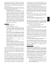
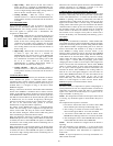
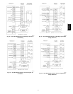
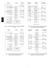
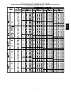
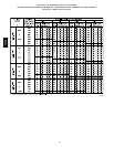
1. Determine natural gas orifice size and manifold pressure
for correct input.
a. Obtainaverageheatvalue(at installedaltitude)fromlocal
gas supplier.
b. Obtain average specific gravity from local gas supplier .
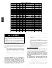
c. Verify furnace model. Table 10 can only be used for
model 355CAV Furnaces.
d. Find installation altitude in Table 10.
NOTE: For Canadian altitudes of 2000 to 4500 ft, use U.S.A.
altitudes of 2001 to 3000 ft in Table 10.
e. Find closest natural gas heat value and specific gravity
in Table 10.
f. Follow heat value and specific gravity lines to point of
intersection to find orifice size and low--, medium--, and
high--heat manifold pressure settings for proper
operation.
EXAMPLE: (0 -- 2000 ft altitude)
Heating value = 1050 Btu/cu ft
Specific gravity = 0.62
Therefore: Orifice No. 45
Manifold pressure: 3.8 --in.wcfor high heat1.6 --in.wcformedium
heat 0.6--in. wc for low heat
* Furnace is shipped with No. 45 orifices. In this example, all main
burnerorifices arethe correct size and do not need to be changed to
obtain proper input rate.
g. Check and verify burner orifice size in furnace. NEVER
ASSUME ORIFICE SIZE; ALWAYS CHECK AND
VERIFY.
2. Adjust manifold pressure to obtain input rate.
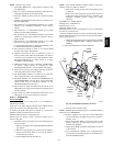
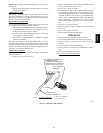
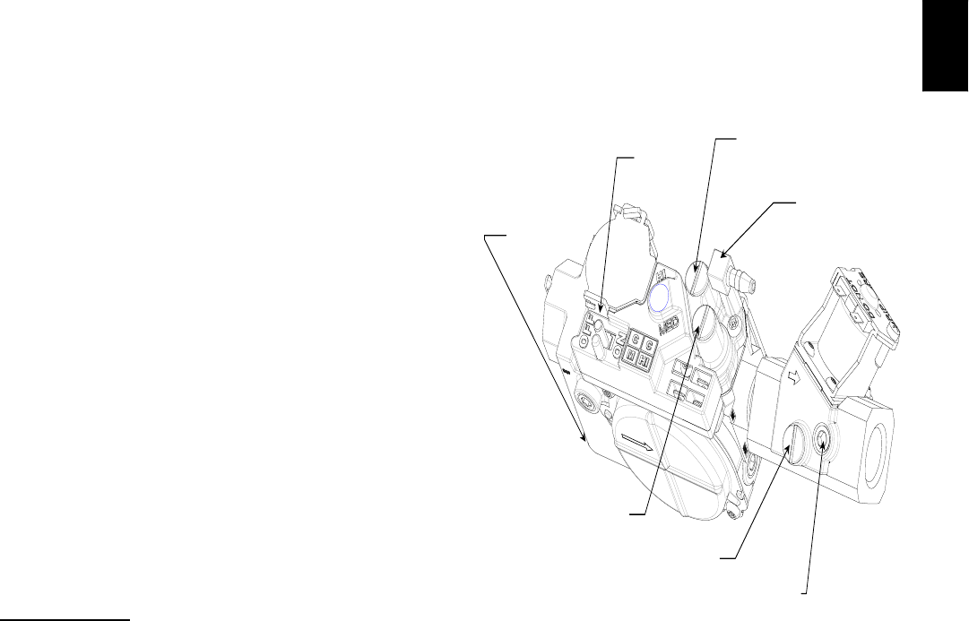
MEDIUM-HEAT
ADJUSTMENT
(UNDER CAP)
INLET
PRESSURE
TAP
ON/OFF
SWITCH
HIGH-HEAT
ADJUSTMENT
(UNDER CAP)
BURNER
ENCLOSURE
REFFERENCE
TAP
LOW-HEAT
ADJUSTMENT
(UNDER CAP)
MANIFOLD
PRESSURE
TAP
A07280
Fig. 60 -- Redundant Automatic Gas Valve
a. Remove burner enclosure front.
NOTE: Manifold pressure MUST always be measured with the
burner box cover REMOVED.
b. Remove regulator seal caps that conceal adjustment
screws for medium-- and high --heat gas valveregulators.
(See Fig. 60.)
c.MovesetupswitchSW4--2oncontrolcentertoON
position. (See Fig. 33.) This keeps furnace locked in
medium--heat operation.
d. Jumper R and W/W1 thermostat connections on control
to start furnace.
e. Turn medium --heat adjusting screw counterclockwise
(out) to decrease manifold pressure or clockwise (in) to
increase manifold pressure.
355CAV