


20
humidifier, or other accessories. All accessories MUST be
connected external to furnace main casing.
Return Air
Connections
FIRE HAZARD
Failure to follow this warning could result in personal injury,
death or property damage.
Never connect return--air ducts to the back of the furnace.
Return air duct c onnections on furnace side(s) permitted in
upflow applications only.
!
WARNING
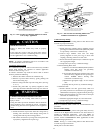
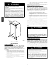
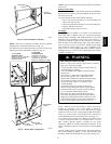
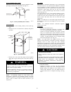
Upflow Furnaces
The return--air duct must be connected to bottom, sides (left or
right), or a combination of bottom and side(s) of main furnace
casing. Bypass humidifier may be attached into unused side
return air portion of t he furnace casing. DO NOT connect any
portion of return--air duct to back of furnace casing.
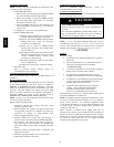
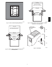
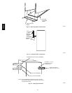
Downflow and Horizontal
Furnaces
The return--air duct must be connected to return--air opening
provided. DO NOT cut into casing sides or back to attach any
portion of return--air duct. Bypass humidifier connections should
be made at ductwork or coil casing sides exterior to furnace.
Filter
Arrangement
FIRE, CARBON MONOXIDE AND POISONING
HAZARD
Failure to follow this warning could result in personal
injury, death or property damage.
Never operate unit without a filter or with filter access door
removed.
!
WARNING
The air filter arrangement will vary due to application, furnace
orientation and filter type. The filter may be installed in an
external Filter/Media cabinet (if provided) or the furnace blower
compartment. Factory supplied washable filters are shipped in the
blower compartment.
If a factory--supplied external Filter/Media cabinet is provided,
instructions for its application, assembly, and installation are
packaged with the cabinet. The Filter/Media cabinet can be used
with the factory--supplied washable filter or a factory--specified
high--efficiency disposable filter (see cabinet instructions).
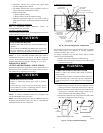
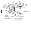
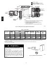
If installing the filter in the furnace blower compartment,
determine location for filter and relocate filter retaining wire, if
necessary. See Table 2 to determine correct filter size for desired
filter location. Table 2 indicates filter size, location, and quantity
shipped with this furnace. See Fig. 2 for location and size of
bottom and side return --air openings.
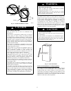
CUT HAZARD
Failure to follow this caution may result in personal injury.
Use care when cutting support rods in filters to protect
against flying pieces and sharp rod ends. Wear safety
glasses, gloves, and appropriate protective clothing.
CAUTION
!
UNIT MAY NOT OPERATE
Failure to follow this caution may result in intermittent unit
operation or performance satisfaction.
For airflow requirements above 1800 CFM, see Air
Delivery table in Product Data literature for specific use of
single side inlets. The use of both side inlets, a combination
of one side and the bottom, or the bottom only will ensure
adequate return air openings for airflow requirements above
1800 CFM.
CAUTION
!
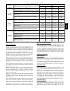
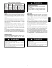
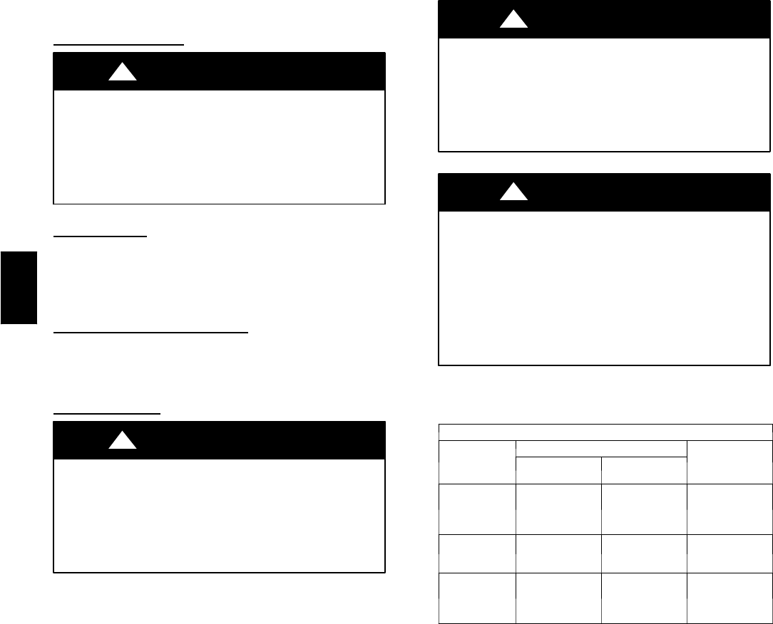
Table 2 – Filter Information
AIR FILTER LOC ATED IN BLOWER COMPARTMENT
Furnace
Casing Width
Filter Size (In./mm)
Filter Type
Framed
Side
Return
Bottom
Return*
17---1/2 in.
(445 mm.)
(1) 16 x 25 x 1
(in.){
406 x 635 x 25
(mm)
(1) 16 x 25 x 1{
406 x 635 x 25
(mm)
Cleanable
21
(533 mm.)
(1) 16 x 25 x 1*
406 x 635 x 25
(mm)
(1) 20 x 25 x 1{
508 x 635 x 25
(mm)
Cleanable
24---1/2
(622 mm.)
(1 or 2)
16 x 25 x 1*
406 x 635 x 25
(mm)
(1) 24 x 25 x 1{
610 x 635 x 25
(mm)
Cleanable
* Filters may be field modified by cutting filter material and support rods (3) in filters.
Alternate sizes canbe ordered from yourdistributor ordealer
{ Factory---provided withthe furnace
355CAV