


32
FURNACE
PIPE DIAMETER
TRANSITION IN
VERTICAL SECTION
NOT IN
HORIZONTAL
SECTION
A93034
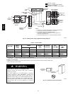
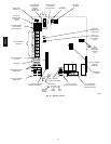
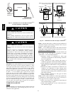
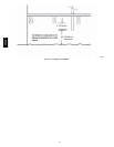
Fig. 38 -- Combustion Air and Vent Pipe Transition
Location and Elbow Configuration
UNIT OPERATION HAZARD
Failure to follow this caution may result in intermittent unit
operation.
When installing combustion air and vent system of short
pipe length, the smallest allowable pipe diameter must be
used.
CAUTION
!
UNIT CORROSION HAZARD
Failure to follow this caution may result in unit component
damage.
Excessive exposure to contaminated combustion air may
result in safety and performance related problems.
Combustion air must not be taken from inside structure
because that air is frequently contaminated by halogens,
which include fluorides, chlorides, bromides, and iodides.
These elements are found in aerosols, detergents, bleaches,
cleaning solvents, salts, air fresheners, adhesives, paint, and
other household products. Locate combustion--air inlet as
far as possible from swimming pool and swimming pool
pump house.
CAUTION
!
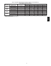
EXAMPLE: This 80,000 BTUH furnace located in Indianapolis,
elevation 650 ft above sea level, could be installed as a direct
vent/2--pipe system that requires 3 elbows and 17 ft of vent pipe,
along with 5 elbows and 16 ft of combustion--air pipe. Table 7
indicates this application would allow a 1--1/2--in. diameter vent
pipe, but require a 2--in. diameter combustion air pipe. According
to Table 7, 1--1/2--in. diameter pipe is good for 20 ft with 3
elbows, but only 10 ft with 5 elbows. Therefore, 2 --in. diameter
pipe must be used for both vent and combustion --air pipes since
the largest required diameter must always be used for both pipes.
If the same installation was made in Albuquerque, elevation 5250
ft above sea level, installation would require 2 -- in. diameter vent
pipe and combustion--air pipe. At 5001 to 6000--ft elevation,
1--1/2--in. pipe is not allowed with 5 elbows, but 2-- in. pipe is
good for 68 ft with 5 elbows are required.
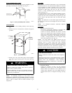
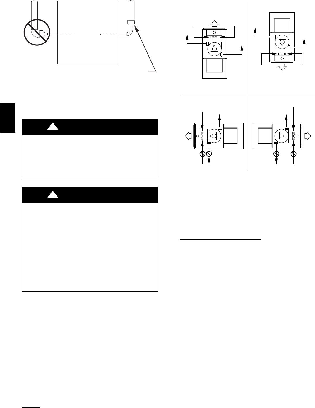
COMBUSTION AIR PIPE
General
Furnace combustion--air connection must be attached as shown in
Fig. 39. Combustion --air intake housing plug may need to be
relocated in some applications.
COMBUSTION-
AIR
COMBUSTION-
AIR
AIR
FLOW
VENT
VENT
VENT
AIR
FLOW
AIR
FLOW
AIR
FLOW
UPFLOW DOWNFLOW
HORIZONTAL-LEFT DISCHARGE HORIZONTAL-RIGHT DISCHARGE
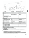
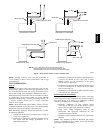
Select 1 vent pipe connection and
1 combustion-air pipe connection.
COMBUSTION-
AIR
COMBUSTION-
AIR
COMBUSTION-
AIR
COMBUSTION-
AIR
VENT
VENT
VENT
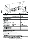
NOTE: Select 1 vent pipe connection and
1 combustion-air pipe connection.
NOTE:
A96187
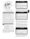
Fig. 39 -- Combustion Air and Vent Pipe Connections
NOTE: All pipe joints must be cemented except a ttachment of
combustion --air pipe to inlet housing connection, since it may be
necessary to remove pipe for servicing.
NOTE: A 2--in. diameter pipe must be used within the furnace
casing. Make all pipe diameter transitions outside furnace casing.
Attachment of Combustion Air
Pipe
NOTE: Combustion air pipe system has the same diameter and
same length as the vent pipe as mentioned in section
“Combustion-- --Air and Vent Pipe Diameter .”
1. Determine location of combustion--air intake pipe
connection to combustion--air intake housing as shown in
Fig. 39 for application.
2. Verify combustion--air intake housing plug fitting is
installed in appropriate unused intake housing connection.
3. Install combustion--air pipe grommet (factory--supplied in
loose parts bag) into selected furnace casing combustionair
pipe hole.
4. Determine the number of combustion air disk halves to be
installed in the combustion air intake housing. Insert
perforated disk half or assembly (factory supplied in loose
parts bag) in intake housing where combustion--air intake
pipe will be connected.
5. Insert assembled combustion air inlet pipe into intake
housing as shown in Fig. 39.
NOTE: Do not cement combustion air intake pipe permanently
to combustion air intake housing since it may be necessary to
remove pipe for service of igniter or flame sensor.
6. Drill a 1/8 --in. hole in 2 --in, combustion air pipe using the
hole in intake housing as a guide.
7. Install a field--supplied No. 6 or No. 8 sheet metal screw
into combustion air pipe.
355CAV