


37
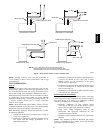
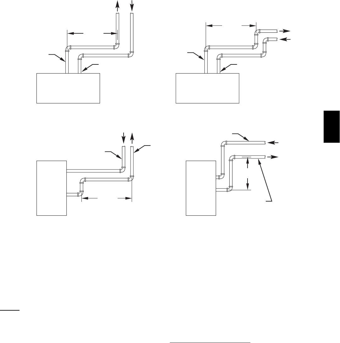
HORIZONTAL TO ROOF HORIZONTAL TO SIDEWALL
VERTICAL TO SIDEWALLVERTICAL TO ROOF
V
ENT PIPE
COMBUSTION-AIR PIPE COMBUSTION-AIR PIPE
VENT PIPE
COMBUSTION-AIR PIPE
VENT PIPE
COMBUSTION-AIR PIPE
VENT PIPE
12″ MIN
12″ MIN
12″ MIN
(304.8mm)
12″ MIN
(304.8mm)
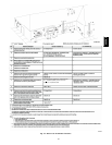
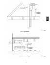
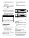
NOTE: A 12-in. (304.8mm) minimum offset pipe section is
recommended with short (5 to 8 ft) vent systems. This
recommendation is to reduce excessive condensate droplets
A96230
Fig. 44 -- Short Vent (5 to 8 Ft or 1.5M -- 2.4M) System
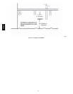
NOTE: Starting at furnace, slope vent pipe a minimum of
1/4--in. (6.4mm) per linear ft back toward furnace with no sags
between hangers.
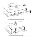
VENT TERMINATION
General
Combustion--air (direct vent/2--pipe system only) and vent pipe
must terminate outside structure, either through sidewall or roof.
For vent termination clearance, refer to Fig. 34 for Direct Vent/2--
Pipe system and Fig. 35 for Ventilated Combustion Air option.
Roof termination is preferred since it is less susceptible to damage
or contamination, and it has less visible vent vapors. Sidewall
termination require sealing or shielding of building surfaces with
a corrosive resistance material due to corrosive combustion
products of vent system.
NOTE: (Direct Vent/2--Pipe system ONLY) A factory accessory
termination kit MUST be used. See section “Vent Termination Kit
(Direct Vent/2--Pipe System Only)” in this instruction.
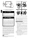
When determining appropriate location for termination, consider
the following guidelines:
1. Comply with all clearance requirements stated in Fig. 34
or Fig. 35 per application.
2. Termination or termination kit should be positioned where
vent vapors will not damage plants/shrubs or air
conditioning equipment.
3. Termination or termination kit should be positioned so that
it will not be affected by wind eddy, such as inside
building corners, nor by recirculation of flue gases,
airborne leaves, or light snow.
4. Termination or termination kit should be positioned where
it will not be damaged by or subjected to foreign objects
such as stones, balls, etc.
5. Termination or termination kit should be positioned where
vent vapors are not objectionable.
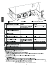
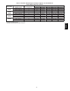
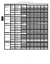
Extended Exposed Sidewall
Pipes
Sidewall combustion air pipe termination (direct vent/2 --pipe
system only) and vent pipe termination may be extended beyond
areashowninFig.36orinFig.37perapplicationinoutside
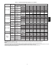
ambient by insulating pipe as indicated in Table 6.
1. Determine combustion air pipe diameter (direct
vent/2--pipe system only) and vent pipe diameter, as stated
above, using total pipe length and number of elbows.
2. Using winter design temperature (used in load
calculations), find appropriate temperature for your
application and furnace model.
3. Determine required insulation thickness for exposed pipe
length(s).
NOTE: Pipe length(ft) specified for maximum pipe lengths
located in unconditioned spaces cannot exceed total allowable
pipe length as specified in Table 6.
355CAV