


58
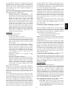
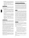
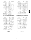
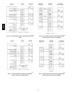
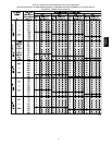
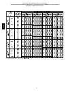
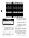
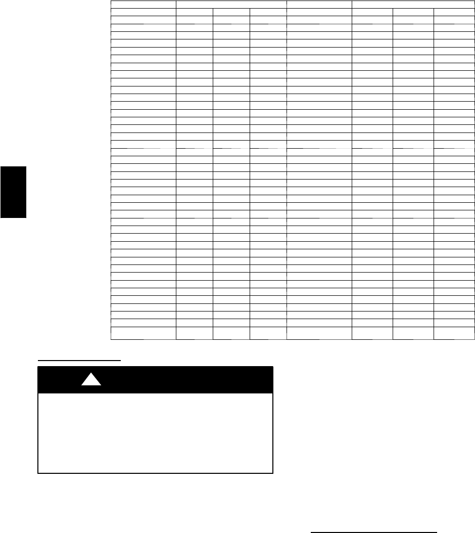
Table12–GasRatecuFt/Hr
SECONDS SIZE OFT E ST DIAL SECONDS SIZE OF TEST DIAL
FOR 1 1 2 5 FOR 1 1 2 5
REVOLUTION cu ft cu ft cu ft REVOLUTION cu ft cu ft cu ft
10 360 720 1800 50 72 144 360
11 327 655 1636 51 71 141 355
12 300 600 1500 52 69 138 346
13 277 555 1385 53 68 136 340
14 257 514 1286 54 67 133 333
15 240 480 1200 55 65 131 327
16 225 450 1125 56 64 129 321
17 212 424 1059 57 63 126 316
18 200 400 1000 58 62 124 310
19 189 379 947 59 61 122 305
20 180 360 900 60 60 120 300
21 171 343 857 62 58 116 290
22 164 327 818 64 56 112 281
23 157 313 783 66 54 109 273
24 150 300 750 68 53 106 265
25 144 288 720 70 51 103 257
26 138 277 692 72 50 100 250
27 133 267 667 74 48 97 243
28 129 257 643 76 47 95 237
29 124 248 621 78 46 92 231
30 120 240 600 80 45 90 225
31 116 232 581 82 44 88 220
32 113 225 563 84 43 86 214
33 109 218 545 86 42 84 209
34 106 212 529 88 41 82 205
35 103 206 514 90 40 80 200
36 100 200 500 92 39 78 196
37 97 195 486 94 38 76 192
38 95 189 474 96 38 75 188
39 92 185 462 98 37 74 184
40 90 180 450 100 36 72 180
41 88 176 439 102 35 71 178
42 86 172 429 104 35 69 173
43 84 167 419 106 34 68 170
44 82 164 409 108 33 67 167
45 80 160 400 110 33 65 164
46 78 157 391 112 32 64 161
47 76 153 383 116 31 62 155
48 75 150 375 120 30 60 150
49 73 147 367
Set Temperature Rise
UNIT DAMAGE HAZARD
Failure to follow this caution may result in component
damage.
Temperature rise must be within limits specified on unit
rating plate. Operation is within a few degrees of midpoint
ofriserangewhensetupswitchSW1--4isoff.
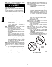
CAUTION
!
Furnace must operate within ranges of temperature rise specified
on the furnace rating plate. Determine air temperature rise as
follows:
1. Place thermometers in return and supply ducts as near
furnace as possible. Be sure thermometers do not see heat
exchanger so that radiant heat does not affect readings.
This practice is particularly important with straight--run
ducts.
2. When thermometer readings stabilize, subtract return--air
temperature from supply--air temperature to determine air
temperature rise.
NOTE: Temperature rise can be determined for low--heat
operation by placing setup switch SW1--2 on furnace control in
ON position. Temperature rise can be determined for
medium--heat operation by placing setup switch SW4--2 on
furnace control in ON position. For high--heat operation, place
setup switch SW1--2 and SW4--2 in OFF position and jumper
R--W2 on furnace control. DO NOT for get to return setup switch
to OFF position and remove R--W2 jumper upon completion of
testing. (See Fig. 33 for switch and terminal location.)
3. This furnace is capable of automatically providing proper
airflow to maintain the temperature rise within the range
specified on furnace rating plate. If temperature rise is
outside this range, proceed as follows:
a. Check gas input for low--, medium-- , and high--heat
operation.
b. Check derate for altitude if applicable.
c. Check all return and supply ducts for excessive
restrictions causing static pressure greater than 0.5--in.
wc.
d. Ensure Low Heat Rise Adjust switch SW1--3 on furnace
control is in ON position when a bypass humidifier is
used. (See Fig. 33 for switch location.)
e. Check Troubleshooting Guide for Variable--Speed Step
Modulating Condensing Furnaces.
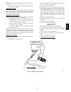
Set Thermostat Heat
Anticipator
When using a non --electronic thermostat, the thermostat heat
anticipator must be set to match the amp draw of components in
the R--W/W1 circuit. Accurate amp draw measurements can be
obtained only at the thermostat subbase terminals R and W.
The thermostat and anticipator should NOT be in the circuit while
measuring current. If thermostat has no subbase, the thermostat
must be disconnected from R and W/W1 wires during current
measurement.
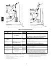
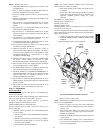
Fig. 63 illustrates an easy method of obtaining thermostat amp
draw measurements. The amp reading should be taken after
blower motor has started and furnace is operating in low--heat.
1. To operate furnace in low--heat, turn setup switch SW1--2
to ON position (See Fig. 33) and connect ammeter leads
across thermostat subbase R-- W.
2. See thermostat manufacturer’s instructions for adjusting
the heat anticipator and for varying heating cycle length.
355CAV