


54
NOTE: DO NOT set medium--heat manifold pressure less than
1.3-- in. wc or more than 1.7 --in. wc for natural gas.
UNIT DAMAGE HAZARD
Failure to follow this caution may result in reduced furnace
life.
DO NOT bottom out gas valve regulator adjusting screws.
This can result in unregulated manifold pressure and result
in excess overfire and heat exchanger failures.
CAUTION
!
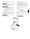
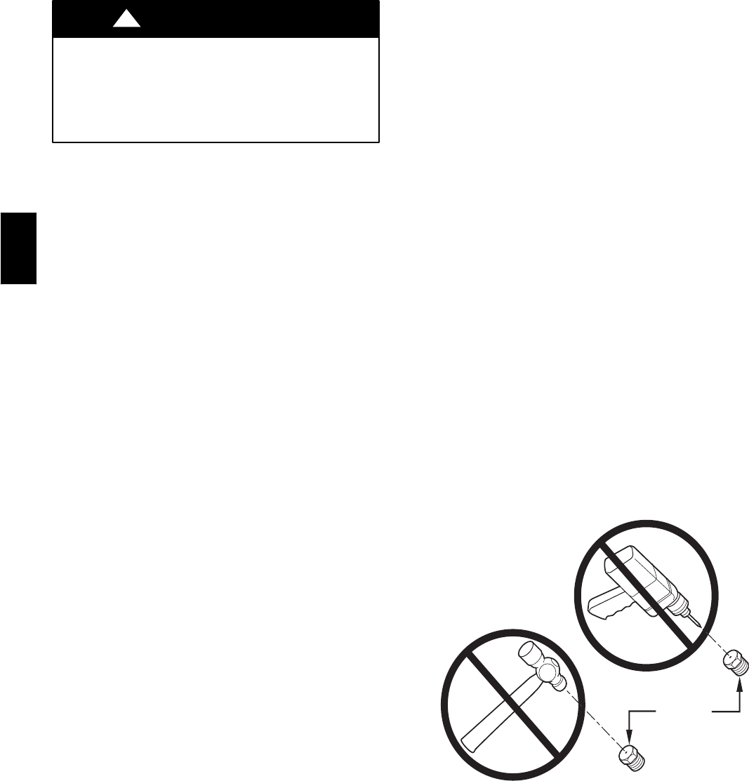
NOTE: If orifice hole appears damaged or it is suspected to have
been redrilled, check orifice hole with a numbered drill bit of
correct size. Never redrill an orifice. A burr--free and squarely
aligned orifice hole is essential for proper flame characteristics.
(See Fig. 61.)
f. Move setup switch SW4--2 to OFF position after
completing medium--heat adjustment.
g. Jumper Rand W/W1and W2thermostatconnectionson
furnace control. (See Fig. 33.) This keeps furnace locked
in high --heat operation.
h. Turn high--heat adjusting screw counterclockwise (out)
to decrease manifold pressure or clockwise (in) t o
increase manifold pressure.
NOTE: DO NOT set high--heat manifold pressure less than
3.2--in. wc or more than 3.8 --in. wc for natural gas.
i. Remove jumpers R to W/W1 and R to W2.
j. Wait for blower off--delay to finish then reset 115--v
power to furnace.
k. Jumper R and W/W1 thermostat connections on control
to start furnace.
l. Wait for the blower to turn ON then check low--heat
manifold pressure. It should be between .5 to .6--in. wc.
This setting should not require adjustment but if it does
remove the low--heat adjustment cap (See Fig. 60) and
turn the low--heat adjusting screw clockwise (in) to
decrease manifold pressure or counterclockwise (out) to
increase manifold pressure. You will only have 15
minutes to make an adjustment if needed. I f you need
more time then move setup s witch SW1--2 on control
center to ON position (See Fig. 33).
NOTE: DO NOT set low--heat ma nifold pressure before setting
medium--heat manifold pressure. DO NOT set low--heat manifold
pressure less than .5 --in. wc or more than .6 --in. wc for natural
gas.
m. When correct manifold pressures are obtained, replace
caps that conceal gas valve adjustment screws. Main
burner flame should be clear blue, almost transparent.
(See Fig. 62.)
n. Remove jumper across R and W/W1. If necessary move
setupswitchSW1--2totheOFFposition.
3. Verify natural gas input rate by clocking gas meter.
NOTE: Be sure all pressure tubing, combustion --air and vent
pipes, and burner enclosure front are in place when checking
input by clocking gas meter.
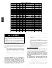
a. Calculate high--altitude adjustment (if required).
UNITED STATES
Ataltitudesabove2000ft,thisfurnacehasbeenapproved
for 2 percent derate for each 1000 ft abovesea level. See
Table 11 for derate multiplier factor and example.
CANADA
Atinstallation altitudesfrom 2000to4500ft,thisfurnace
must be derated 5 percent by an authorized Gas
Conversion Station orDealer.To determine correctinput
rate for altitude, see example and use 0.95 as derate
multiplier factor.
EXAMPLE: 80,000 BTUH HIGH--HEAT INPUT
FURNACE INSTALLED AT 4,300 FT
Furnace Input Rate at Sea Level X Derate Multiplier
Factor = Furnace Input Rate at Installation Altitude
80,000 X 0.91 = 72,800
b. Reinstall burner box cover.
NOTE: Clocking gas input rate MUST always be performed
with the burner box cover INSTALLED.
c. Check that gas valve adjustment caps are in place for
proper input to be clocked.
d. Obtain average heat value (at altitude) from local gas
supplier.
NOTE: Be sure heating value of gas used for calculations is
correct for your altitude. Consult local gas utility for altitude
adjustment of gas heating value.
e. Check and verify orifice size in furnace. NEVER
ASSUME THE ORIFICE SIZE. ALWAYS CHECK
AND VERIFY.
f. Turn of f all other gas appliances and pilots.
g. MovesetupswitchSW4 --2toONposition.(SeeFig.33.)
This keeps furnace locked in medium-- heat operation.
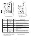
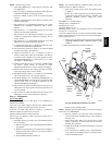
BURNER
ORIFICE
A93059
Fig. 61 -- Burner Orifice
355CAV