


12
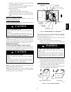
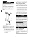
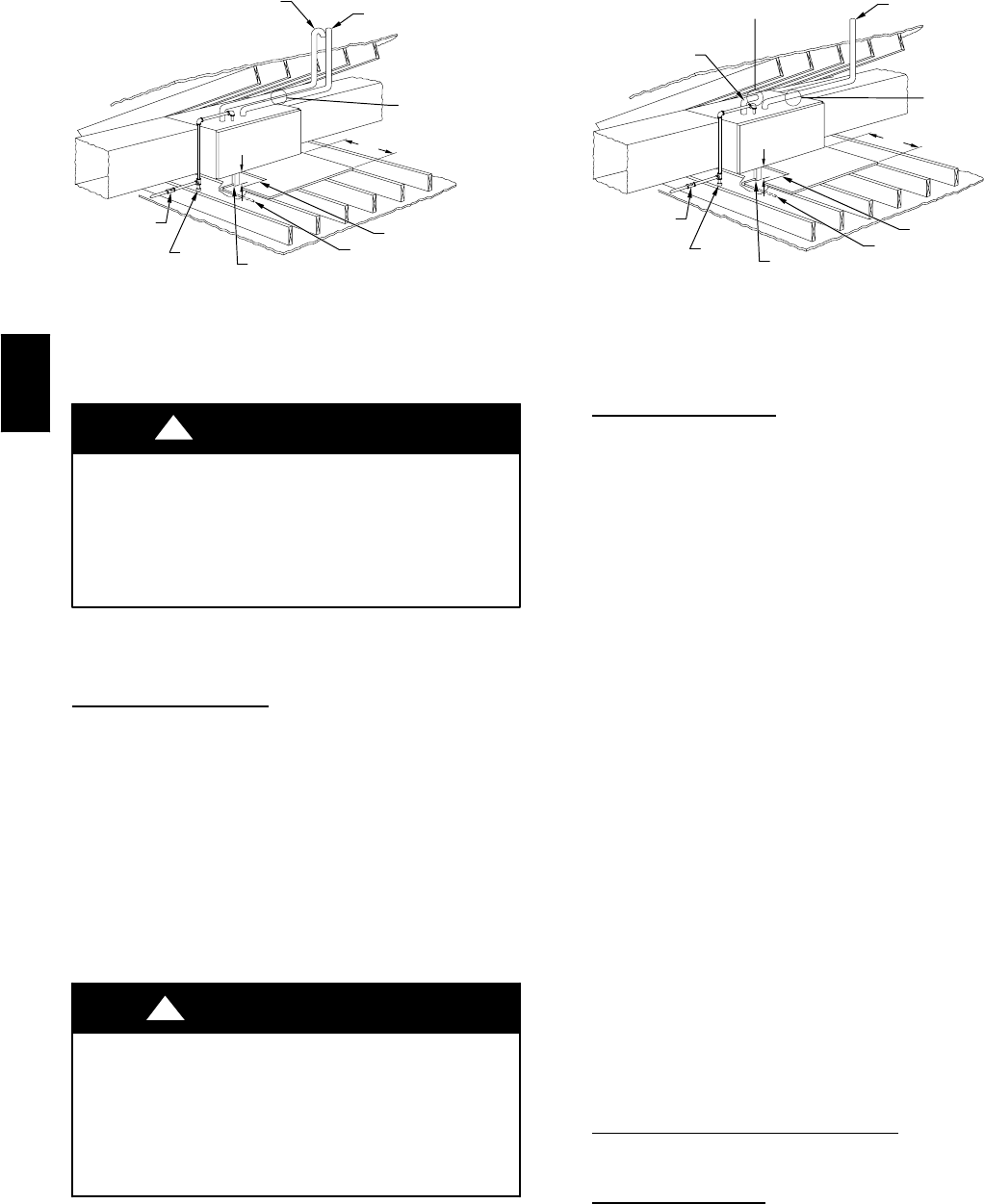
COMBUSTION – AIR
INTAKE
VENT
MANUAL
SHUTOFF
GAS VALVE
SEDIMENT
TRAP
CONDENSATE
TRAP
DRAIN
ACCESS OPENING
FOR TRAP
30″ MIN
WORK AREA
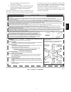
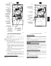
A 12-IN. MIN HORIZONTAL PIPE
SECTION IS RECOMMENDED WITH
SHORT (5 TO 8 FT) VENT SYSTEMS
TO REDUCE EXCESSIVE
CONDENSATE DROPLETS FROM
EXITING THE VENT PIPE.
5
3
⁄
4
″
NOTE: LOCAL CODES MAY REQUIRE A DRAIN PAN UNDER THE
FURNACE AND CONDENSATE TRAP WHEN A CONDENSING
FURNACE IS INSTALLED ABOVE FINISHED CEILINGS.
A93031
Fig. 12 -- Attic Location and Working Platform for Direct
Vent (2 --Pipe) Application
PROPERTY DAMAGE
Failure to follow this caution may result in property
damage.
Local codes may require a drain pan under entire furnace
and condensate trap when a condensing furnace is used in
an attic application or over a finished ceiling.
CAUTION
!
NOTE: In Canada, installations shall be in accordance with
current NSCNGPIC and/or local codes.
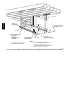
Condensate Trap
Location
The condensate trap must be removed from the factory--installed
blower shelf location and relocated in selected application
location as shown in Fig. 2 or 11.
To relocate condensate trap from the blower shelf to desired
location, perform the following:
1. Remove three tubes connected to condensate trap.
2. Remove trap from blower shelf by gently pushing tabs
inward and rotaing trap.
3. Remove casing hole filler cap from casing hole. (See Fig.
2or11.)
4. Install casing hole filler cap (factory--supplied in loose
parts bag) into blower shelf hole where trap was removed.
CARBON MONOXIDE POISONING HAZARD
Failure to follow this warning could result in personal
injury or death.
Casing hole filler cap must be installed in blower shelf hole
when condensate trap is relocated to prevent combustion
products being drawn in from appliances in the equipment
room.
!
WARNING
5. Install condensate trap into left--hand side casing hole by
inserting tube connection stubs through casing hole an
rotating until tabls snap into locking position.
6. Fill unused condensate trap casing holes with plastic filler
caps (factory--supplied in loose parts bag).
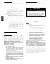
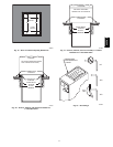
VENT
MANUAL
SHUTOFF
GAS VALVE
SEDIMENT
TRAP
CONDENSATE
TRAP
DRAIN
ACCESS OPENING
FOR TRAP
30-IN. MIN
WORK AREA
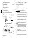
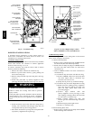
A 12-IN. MIN HORIZONTAL PIPE
SECTION IS RECOMMENDED WITH
SHORT (5 TO 8 FT) VENT SYSTEMS
TO REDUCE EXCESSIVE
CONDENSATE DROPLETS FROM
EXITING THE VENT PIPE.
A 3-IN. MINIMUM CLEARANCE
TO COMBUSTION-AIR INTAKE
IS REQUIRED.
5
3
⁄
4
″
NOTE: LOCAL CODES MAY REQUIRE A DRAIN PAN UNDER THE
FURNACE AND CONDENSATE TRAP WHEN A CONDENSING
FURNACE IS INSTALLED ABOVE FINISHED CEILINGS.
COMBUSTION–AIR
INTAKE
A96184
Fig. 13 -- Attic Location and Working Platform for
Ventilated Combustion Air Applications
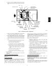
Condensate Trap T
ubing
NOTE: See Fig. 11 or tube routing label on main furnace door
to check for proper connections.
1. Collector Box DrainTube
a. Install drain tube coupling (factory --supplied in loose
partsbag)intocollectorboxdraintube(bluelabel)which
was previously connected to condensate trap.
b. Connect lar ge diameter drain tube and clamp
(factory--supplied in loose parts bag) to drain tube
coupling, extending collecor box drain tube.
c. Route extended tube (blue label) to condensate trap and
cut to appropriate length.
d. Clamp tube to prevent any condensate leakage.
2. Inducer Housing Drain Tube
(a.)Remove and discard LOWER (molded) inducer
housing drain tube which was previously
connected to condensate trap.
(b.)Use inducer housing drain extension tube (violet
label and factory--supplied in loose parts bag) to
connect LOWER inducer housing drain
connection to condensate trap.
(c.)Determine appropriate length, cut and connect
tube.
(d.)Clamp tube to prevent any condensate leakage.
3. Relief Port Tube
a. Extend collector box tube (green label) which was
previously connected to condensate trap by splicing to
smalldiametertube(factory--suppledin loosepartsbag).
b. Route extended collector box pressur tube to relief port
connectio on condensate trap.
c. Determine appropriate length, cut, and connect tube.
d. Clamp tube to prevent any condensate leakage.
Condensate Trap Field Drain
Attachment
Refer to Condensate Drain section for recommendations and
procedures.
Pressure Switch T
ubing
The LOWER collector box pressure tube (pink label) is factory
connected to the High Pressure Switch for use when furnace is
installed in UPFLOW applications. This tube MUST be
disconnected, extended rerouted, and then reconnected to the
pressure switch in HORIZONTAL LEFT applications for 060
and 080 heating input furnaces.
NOTE: See Fig. 11 or tube routing label on main furnace door
to check for proper connections.
Modify tube as described below.
355CAV