


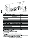
38
Vent Termination Kit (Direct Vent/2--Pipe System
Only)
NOTE: Always refer to the instructions in termination kit for the
latest version.
Combustion air and vent pipes MUST terminate outside structure.
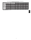
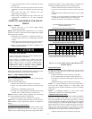
A factory accessory termination kit must be installed as shown in
Table 8. There are four options of vent/combustion air
termination kits available as shown in Table 8.
NOTE: Combustion air pipe must have the same diameter as
vent pipe.
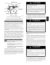
Concentric Vent / Combustion Air Termination Kit (Dir
ect
Vent / 2--Pipe System
Only
Determine an appropriate location for termination kit using the
guidelines provided in section “Vent Termination: General” in
this instruction.
1. Cut one 4--in. diameter hole for 2--in. kit, or one 5--in.
diameter hole for 3--in. kit.
2. Loosely assemble concentric vent/combustion air
termination components together using instructions in kit.
3. Slide assembled kit with rain shield REMOVED through
hole.
NOTE: Do not allow insulation or other materials to accumulate
inside of pipe assembly when installing it through hole.
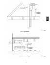
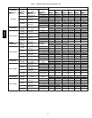
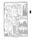
Roof terminations--Locate assembly through roof to appropriate
height as shown in Fig. 36 or Fig. 37.
Sidewall terminations-- Locate assembly through sidewall with
rain shield positioned no more than 1--in (25.4mm). from wall as
shown in Fig. 36 and Fig. 37.
4. Disassemble loose pipe fittings. Clean and cement using
same procedures as used for system piping.
5. Check required dimensions as shown.
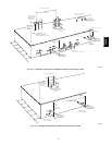
Two--Pipe Termination Kit (Dir ect Vent/2--Pipe System
Only)
Determine an appropriate location for termination kit using the
guidelines provided in section “Vent Termination: General” in
this instruction.
1. Cut 2 holes, 1 for each pipe, of appropriate size for pipe
size being used.
2. Loosely install elbow in bracket and place assembly on
combustion --air pipe.
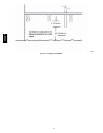
Roof terminations--Loosely install pipe coupling on
properly cut vent pipe. Coupling must be positioned so
bracket will mount as shown in Fig. 38.
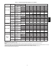
For applications using combustion--air pipe option, indicated by
dashed lines in Fig. 36, install 90_ street elbow into 90_ elbow,
making a U--fitting. A 180_ U--fitting may be used.
Sidewall terminations--Install bracket as shown in Fig. 36.
For applications using vent pipe option indicated by dashed lines
in Fig. 36, rotate vent elbow 90_ from position shown in Fig. 36
.
3. Disassemble loose pipe fittings. Clean and cement using
same procedures as used for system piping.
4. Check required dimensions as shown in Fig. 36.
(Direct Vent/2 --Pipe System ONLY)--When 2 or more 355CAV
furnaces are vented near each other , 2 vent t erminations may be
installed as shown in Fig. 36, but next vent termination must be at
least 36 in. (914.4mm) away from first 2 terminations. It is
important that vent terminations be made as shown in Fig. 36 to
avoid recirculation of flue gases.
355CAV