


7
S The use of copper tubing for gas piping is not approved
by the state of Massachusetts.
Electrical
Connections
S US: National Electrical Code (NEC) ANSI/NFPA
70--2005.
S CANADA: Canadian Electrical Code CSA C22.1.
ELECTROSTATIC DISCHARGE ( ESD)
PRECAUTIONS
UNIT DAMAGE HAZARD
Failure to follow this caution may result in damage to unit
components.
Electrostatic discharge can affect electronic components.
Take precautions during furnace installation and servicing
to protect the furnace electronic control. Precautions will
prevent electrostatic discharges from personnel and hand
tools which are held during the procedure. These
precautions will help to avoid exposing the control to
electrostatic discharge by putting the furnace, the control,
and the person at the same electrostatic potential.
CAUTION
!
3. Disconnect all power to the furnace. Multiple disconnects
may be required. DO NOT TOUCH THE CONTROL OR
ANY WIRE CONNECTED TO THE CONTROL PRIOR
TO DISCHARGING YOUR BODY’S
ELECTROSTATIC CHARGE TO GROUND.
4. Firmly touch a clean, unpainted, metal surface of the
furnace chassis which is close to the control. Tools held in
a person’s hand during grounding will be satisfactorily
discharged.
5. After touching the chassis, you may proceed to service the
control or connecting wires as long as you do nothing that
recharges your body with static electricity (for example;
DO NOT move or shuffle your feet, DO NOT touch
ungrounded objects, etc.).
6. If you touch ungrounded objects (recharge your body with
static electricity), firmly touch furnace again before
touching control or wires.
7. Use this procedure for installed and uninstalled
(ungrounded) furnaces.
8. Before removing a new control from its container,
discharge your body’s electrostatic charge to ground to
protect the control from damage. If the control is to be
installed in a furnace, follow items 1 through 5 before
bringing the control or yourself into contact with the
furnace. Put all used AND new controls into containers
before touching ungrounded objects.
9. An ESD service kit (available from commercial sources)
mayalsobeusedtopreventESDdamage.
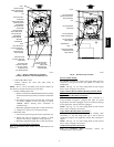
INTRODUCTION
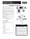
The model 355CAV Direct Vent, Upflow, Gas--Fired, Category
IV, condensing furnace is available in model sizes ranging in
input capacities of 60,000 to 120,000 Btuh.
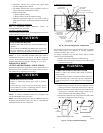
APPLICATIONS
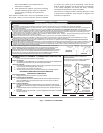
General
Some assembly and modifications are required for furnaces
installed in any of the four applications shown in Fig. 1. All
drain and pressure tubes are connected as shown in Fig. 7. See
appropriate application instructions for these procedures.
PROPERTY DAMAGE HAZARD
Failure to follow this caution may result in property
damage.
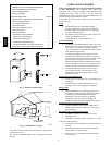
Local codes may require a drain pan under entire furnace
and condensate trap when a condensing furnace is used in
an attic application or over a finished ceiling.
CAUTION
!
NOTE: In Canada, installations shall be in accordance with
current CAN/CSA --B149.1--05 and/or local codes.
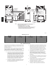
UPFLOW APPLICATION
An upflow furnace application is where furnace blower is located
below combustion and controls section of furnace, and
conditioned air is discharged upwards.
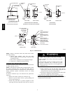
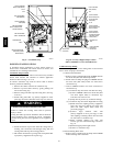
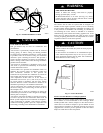
Condensate Trap (Factory--Shipped
Orientation)
The condensate trap is factory installed in the blower shelf and
factory connected for UPFLOW applications. A factory--supplied
tube is used to extend the condensate trap drain connection to the
desired furnace side for field drain attachment. See Condensate
Trap Tubing section for drain tube extension details. (See Fig. 6.)
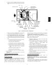
Condensate Trap Tubing (Factory--Shipped
Orientation)
NOTE: See Fig. 7 or tube routing label on main furnace door to
confirm location of these tubes.
1. Collector Box Drain, I nducer Housing Drain, Relief Port,
and Pressure Switch Tubes.
These tubes should be factory attached to condensate trap
andpressureswitchreadyforuseinUPFLOW
applications. These tubes can be identified by their
connection location and also by a c olor label on each tube.
These t ubes are identifed as follows: collector box drain
tube (blue label), inducer housing drain tube (violet label
or molded), relief port tube (green label), and pressure
switch tube (pink label).
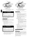
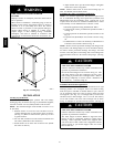
2. Condensate Trap Drain Tube
The condensate trap drain connection must be extended
for field attachment by doing the following:
f. Determine location of field drain connection. (See Fig.
2or7.)
NOTE: If internal filter or side filter/media cabinet is used, drain
tube should be located to opposite side of casing from return duct
attachment to assist in filter removal.
g. Remove and discard casing drain hole plug button from
desired side.
h. Installdraintubecouplinggrommet(factory--suppliedin
loose parts bag) in selected casing hole.
i. Slidedrain tubecoupling (factory--suppliedin looseparts
bag) through grommet so long end of coupling faces
blower.
j. Cement 2 factory--supplied 1/2--in. (12.7mm) street
CPVC elbows to rigid drain tube connection on
condensate trap. (See Fig. 7.) These elbows must be
cementedtogetherandcementedtocondensatetrapdrain
connection.
355CAV