


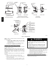
16
Hazardous
Locations
FIRE, EXPLOSION, INJURY OR DEATH
HAZARD
Improper location or inadequate protection could result in
fire or explosion.
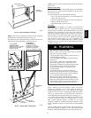
When furnace is installed in a residential garage, it must be
installed so that burners and ignition sources are located a
minimum of 18 in. (457.2mm) above floor. The furnace
must be located or protected to avoid physical damage by
vehicles. When furnace is installed in a public garage,
airplane hangar , or other building having a hazardous
atmosphere, unit must be installed in accordance with
requirements of National Fire Protection Association, Inc.
(See Fig. 5.)
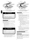
!
WARNING
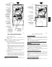
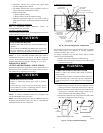
1
3
⁄4″
1
3
⁄4″
1
3
⁄4″
1
3
⁄4″
5
⁄16″
5
⁄16″
5
⁄16″
5
⁄16″
A89014
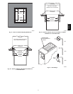
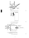
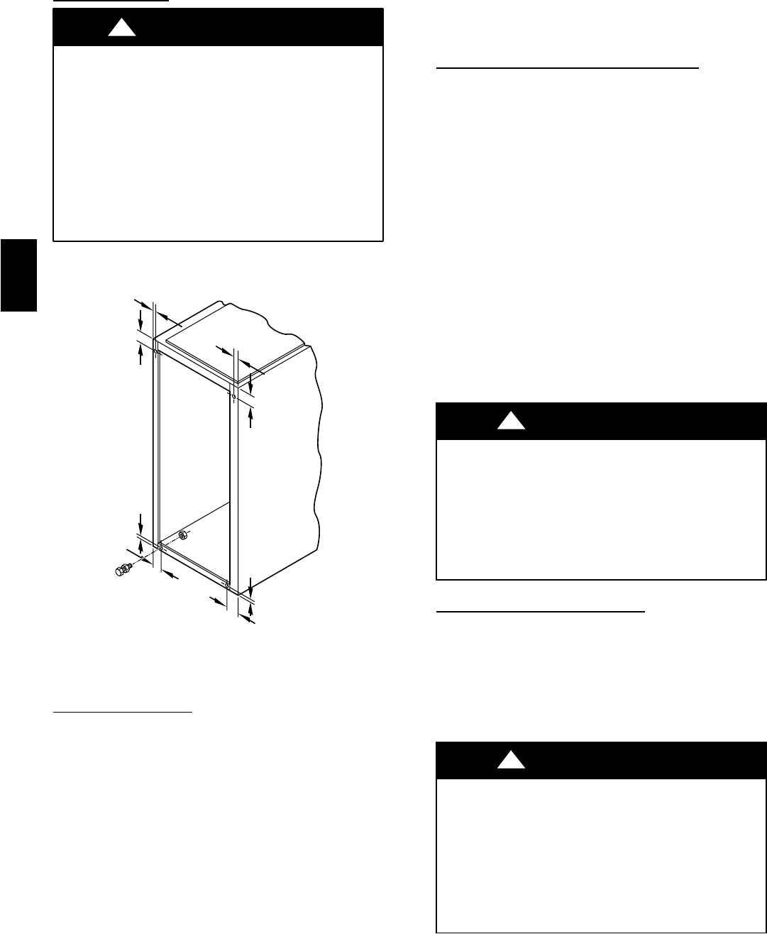
Fig. 18 -- Leveling Legs
INSTALLATION
Leveling Legs (If Desired)
When furnace is used in upflow position with side inlet(s),
leveling legs may be desired. (See Fig. 18.) Install field--supplied,
corrosion--resistant 5/16--in.(7.9mm) machine bolts and nuts.
NOTE: The maximum length of bolt should not exceed 1--1/2
in. (38.1mm).
1. Position furnace on its back. Locate and drill a 5/16--in.
(7.9mm) diameter hole in each bottom corner of furnace.
(See Fig. 18.) Holes in bottom closure panel may be used
as guide locations.
2. For each hole, install nut on bolt and then install bolt and
nut in hole. (Install flat washer if desired.)
3. Install another nut on other side of furnace base. (Install
flat washer if desired.)
4. Adjust outside nut to provide desired height, and tighten
inside nut to secure arrangement.
NOTE: Bottom closure must be used when leveling legs are
used. See Bottom Closure Panel section.
Installation in Upflow or Downflow
Applications
NOTE: For downflow applications, this furnace is approved for
use on combustible flooring when special base (available from
Manufacturer) Part No. KGASB is used. Special base is not
required when this furnace is installed on Manufacturer’s Cased
Coil Assembly or when Manufacturer’s Coil Box is used.
1. Determine application being installed from Table 1.
2. Construct hole in floor per dimensions specified in Table 1
and Fig. 19.
3. Construct plenum to dimensions specified in Table 2 and
Fig. 19.
4. If special base (KGASB) is u sed, install as shown in Fig.
20.
5. If Manuracturer’s Cased Coil Assembly or Manufacturer’s
Coil Box is used, install as shown in Fig. 21.
NOTE: Remove furnace perforated discharge duct flanges when
they interfere with mating flanges on coil on downflow subbase.
To remove furnace perforated discharge duct flange, use hand
scanners, wide duct pliers or duct flange tool to bend flange back
and forth until it breaks off. Be careful of sharp edges. (See Fig.
22.)
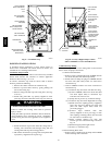
UNIT MAY NOT OPERATE HAZARD
Failure to follow this caution may result in intermittent unit
operation or performance satisfaction.
Do not bend duct flanges inward as shown in Fig. 22. This
will affect airflow across heat exchangers and may cause
limit cycling or premature heat exchanger failure. Remove
duct flange completely or bend it inward a minimum of
210_F(99_C) as shown in Fig. 22.
CAUTION
!
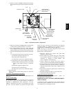
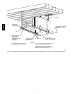
Installation in Horizontal Applications
These f urnaces can be installed in either horizontal left or right
discharge position. In a crawlspace, furnace can either be hung
from floor joist or installed on suitable blocks or pad. Furnace
can be suspended from each corner by hanger bolts and angle
iron supports. (See Fig. 23.) Cut hanger bolts (4 each 3/8--in.
all--thread rod) to desired length. Use 1 X 3/8 --in. flat washers,
3/8--in. lock washers, and 3/8--in. nuts on hanger rods as shown
in Fig. 23. Dimples are provided for hole locations. (See Fig. 2.)
UNIT MAY NOT OPERATE HAZARD
Failure to follow this caution may result in intermittent unit
operation or performance satisfaction.
The entire length of furnace MUST be supported when
furnace is used in a horizontal position to ensure proper
draining. When suspended, bottom brace supports sides
and center blower shelf. When unit is supported from the
ground, blocks or pad should support sides and center
blower shelf area.
CAUTION
!
355CAV