


47
Purge Gas
Lines
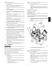
If not previously done, purge the lines after all connections have
been made and check for leaks.
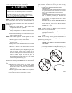
FIRE AND EXPLOSION HAZARD
Failure to follow this caution could result in a fire,
explosion, personal injury, or death.
Never purge a gas line into a combustion chamber. Never
test for gas leaks with an open flame. Use a commercially
available soap solution made specifically for the detection
of leaks to check all connections.
CAUTION
!
Step 3 — Sequence of Operation
UNIT OPERATION HAZARD
Failure to follow this caution may result in intermittent unit
operation.
Furnace control must be grounded for proper operation, or
control will lock out. Control is grounded through
green/yellow wire routed to gas valve and burner box
screw .
CAUTION
!
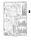
Using the schematic diagram (See Fig. 48), follow the sequence
of operation through the different modes. Read and follow the
wiring diagram very carefully. ! !
NOTE: If a power interruption occurs during a call for heat
(W/W1 or W/W1 --and--W2), the control will start a 90--second
blower--only ON period two seconds after power is restored, if
the thermostat is still calling for gas heating. The amber LED
light will flash code 12 during the 90--second period, after which
the LED will be ON continuous, as long as no faults are detected.
After the 90--second period, the furnace will respond to the
thermostat normally.
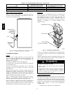
The blower door must be installed for power to be conducted
through the blower door interlock switch ILK to the furnace
control CPU, transformer TRAN, inducer motor IDM, blower
motor BLWM, hotsurface igniter HSI, throttling valve TV, and
gas valve GV.
Single--Stage Thermostat and Step--Modulating
Heating
(Adaptive
Mode)
See Fig. 29 or Fig. 59 for thermostat connections.
NOTE: Low--heat only switch SW1--2 selects the low--heat only
operation mode when ON. Medium--heat only switch SW4 --2
selects medium-- heat only operation mode when ON. If both
switches are ON the furnace control will default to medium--heat.
If either or both switches are ON the furnace control will operate
at two--stages only as referenced in Section 2 below. If both
switches are OFF the furnace control will operate in the adaptive
heating mode in response to a call for heat. (See Fig. 33.) When
the W2 thermostat terminal is energized it will always cause
high--heat operation as long as the R to W circuit is closed,
regardless of the setting of the low--heat or medium--heat only
switches.
This furnace can operate as a step--modulating furnace with a
single--stage thermostat because the furnace control CPU includes
a programmed adaptive sequence of controlled operation, which
selects low--heat, medium--heat, or high--heat operation. This
selection is based upon the stored history of the length of
previous gas-- heating periods of the single-- stage thermostat.
The furnace will start up in either medium--, or high--heat. The
furnace will operate in low--heat after starting and operating for 1
minute at medium--heat before transitioning to low--heat. The
furnace control CPU determines the combined low --heat and
medium--heat on--time (from 0 to 16 minutes) which is permitted
before switching to high heat.
If the power is interrupted, the stored history is erased and the
furnace control CPU will select medium--heat for 1 minute,
low--heat for 15 minutes and then switch to high--heat, as long as
the thermostat continues to call for heat. Subsequent selection is
based on stored history of the thermostat cycle times.
The wall thermostat ”calls for heat”, closing the R to W circuit.
The furnace control CPU performs a self--check, verifies the
low--heat and medium--heat pressure switch contacts LPS and
MPS are open, then de--energizes the HPSR relay to close the NC
contact.
1. Inducer Prepurge Period -- The furnace control CPU turns
on inducer motor IDM and slowly increases the inducer
motor speed. After the low--heat pressure switch LPS
closes the furnace control CPU continues to increase the
inducer motor speed until the medium--heat pressure
switch MPS closes. When the medium--heat pressure
switch MPS closes, t hrottling valve TV is energized,
inducer motor RPM is noted by the furnace control CPU,
and a 25 --second prepurge period begins. The RPM is
used to evaluate vent system resistance. This evaluation is
then used to determine the required RPM necessary to
operate the inducer motor during medium--heat prepurge,
the first minute of medium-- heat mode, and low--heat
mode.
NOTE: The heat cycle can start in either high-- or medium--heat.
If a high--heat cycle is initiated, the furnace control CPU will
continue to increase the inducer motor speed after t he
medium--heat pressure switch MPS closes. When the
medium--heat pressure switch closes, throttling valve TV is
energized, inducer motor RPM is noted by the furnace control
CPU, and a 25--second prepurge period begins. The RPM is used
to evaluate vent system resistance. This evaluation is then used to
determine the required RPM necessary to operate the inducer
motor in high --heat pre--purge, and high--heat mode.
2. Igniter Warm--Up — At the end of the prepurge period,
the Hot--Surface Igniter HSI is ener gized for a 17--second
igniter warm--up period.
3. Trial--For--Ignition Sequence — When the igniter
warm--up period is completed the main gas valve relay
contact GVR closes to energize the gas valve solenoid
GV--M. The gas valve solenoid GV--M permits gas flow
to the burners where it is ignited. Five seconds after the
GVR closes, a 2-- second Flame--Proving period begins.
The HSI igniter will remain energized until flame is sensed
or until the 2--second flame proving period begins.
If the furnace control CPU selects high --heat operation, the
high--heat gas valve solenoid GV --HI is energized when
the high--heat pressure switch HPS closes.
4. Flame--Proving — When the burner flame is proved at the
flame--proving sensor electrode FSE, the furnace control
CPU begins the blower-- ON delay period and continues to
hold the gas valve GV--M open. If the burner flame is not
proved within two seconds, the furnace control CPU will
close the gas valve GV --M, and the furnace control CPU
will repeat the ignition sequence for up to three more
Trials--For--Ignition before going to Ignition--Lockout.
Lockout will be reset automatically after three hours, by
momentarily interrupting 115 vac power to the furnace, or
by interrupting 24 vac power at SEC1 or SEC2 to the
furnace control CPU (not at W/W1, G, R, etc.).
If flame is proved when flame should not be present, the
furnace control CPU will lock out of Gas--Heating mode
355CAV