


27
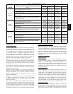
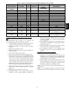
Table 5 – Approved Combustion--Air and Vent Pipe, Fitting and Cement Materials
ASTM
SPECIFICATION MATERIAL PIPE FITTINGS
SOLVENT
CEMENT
DESCRIPTION
(MARKED ON
MATERIAL)
AND PRIMERS
D1527 ABS Pipe — — Schedule40
D1785 PVC Pipe — — Schedule40
D2235 For ABS — — Solvent For ABS
Cement
D2241 PVC Pipe — — SDR21 & SDR26
D2466 PVC — Fittings — Schedule40
D2468 ABS — Fittings — Schedule40
D2564 For PVC — — Solvent For PVC
Cement
D2661 ABS Pipe Fittings — DWV at Schedule40 IPS sizes
D2665 PVC Pipe Fittings — DWV
F438 CPVC — Fittings — Schedule40
F441 CPVC Pipe — — Schedule40
F442 CPVC Pipe — — SDR
F493 For CPVC — — Solvent For CPVC
Cement
F628 ABS Pipe — —
Cellular Core DWV at Schedule40
IPS sizes
F656 ForPVC — — Primer For PVC
F891 PVC Pipe — —
Cellular Core Schedule40 &
DWV
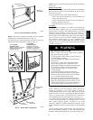
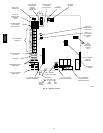
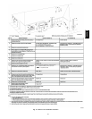
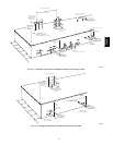
Installation Guidelines for Combustion Air Pipe and Vent
Pipe
It is recommended that all pipes be cut, prepared, and
preassembled before permanently cementing any joint.
1. Attach combustion air pipe and vent pipe per instructions
in sections “Combustion Air Pipe” and “Vent Pipe.”
2. Working from furnace to outside, cut pipe to required
length(s).
3. Deburr inside and outside of pipe.
4. Chamfer outside edge of pipe for better distribution of
primer and cement.
5. Clean and dry all surfaces to be joined.
6. Check dry fit of pipe and mark insertion depth on pipe.
7. After pipes have been cut and preassembled, apply
generous layer of cement primer to pipe fitting socket and
end of pipe to insertion mark. Quickly apply approved
cement to end of pipe and fitting socket (over primer).
Apply cement in a light, uniform coat on inside of socket
to prevent buildup of excess cement. Apply second coat.
8. While cement is still wet, twist pipe into socket with 1/4
turn. Be sure pipe is fully inserted into fitting socket.
9. Wipe excess cement from joint. A continuous bead of
cement will be visible around perimeter of a properly
made joint.
10. Handle pipe joints carefully until cement sets.
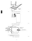
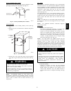
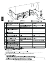
11. Horizontal portions of the venting system shall be
supported to prevent sagging. Support combustion air
piping and vent piping a minimum of every 5 ft (1.5 m)(3
ft (.91 m) for SDR--21 or --26 PVC) using perforated
metal hanging strap.
12. Slope combustion air piping and vent piping downward
towards furnace a minimum of 1/4 --in. per linear ft with no
sags between hangers.
13. Horizontal portions of the venting system shall be installed
so as to prevent the accumulation of condensate.
14. Use appropriate methods to seal openings where
combustion air pipe and vent pipe pass through roof or
sidewall.
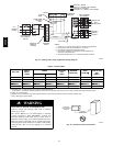
Combustion--Air and Vent Pipe
Diameter
Determine combustion--air and vent pipe diameter.
1. Using Table 7, individually determine the diameter of the
combustion--air and vent pipe allowed. If different, pick
the larger of these two diameters and use this diameter for
both combustion--air and vent pipes.
2. When installing vent systems of short pipe length, use the
smallest allowable pipe diameter . Do not use pipe size
greater than required or incomplete combustion, flame
disturbance, or flame sense lockout may occur.
NOTE: Do not count elbows or pipe sections in terminations or
within furnace.
NOTE: A 2--in. diameter pipe must be used within furnace
casing. Make all pipe diameter transitions outside furnace casing.
355CAV