


50
2. High cooling –WhentheRtoG--andY/Y2circuitis
closed and there is a demand for dehumidification, the
furnace blower motor BLWM will drop the blower airflow
to 86% of high --cooling airflow. High--cooling airflow is
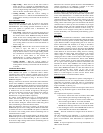
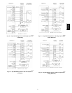
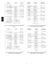
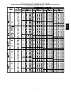
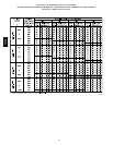
basedontheA/CselectionshowninFig.47.
3. Cooling off--delay – When the “call for cooling” is
satisfied and there is a demand for dehumidification, the
cooling blower-- off delay is decreased from 90 seconds to
5 seconds.
Super Dehumidify
Mode
Super--Dehumidify mode can only be entered if the furnace
control is in the Thermidistat mode and there is a demand for
dehumidification. The cooling operation described in item 4.
above also applies to operation with a Thermidistat. The
exceptions are listed below:
1. Low cooling –WhentheRtoY1circuitisclosed,RtoG
circuit is open, and there is a demand for dehumidification,
the furnace blower motor BLWM will drop the blower
airflow to 65% of low--cooling airflow for a maximum of
10 minutes each cooling cycle or until the R to G circuit
closes or the demand for dehumidification is satisfied.
Low--cooling airflow is the true on--board CF selection as
shown in Fig. 47.
2. High cooling – When the R to Y/Y2 circuit is closed, R to
G circuit is open, and there is a demand for
dehumidification, the furnace blower motor BLWM will
drop the blower airflow to 65% of high--cooling airflow
for a maximum of 10 minutes each cooling cycle or until
the R to G circuit closes or the demand for
dehumidification is satisfied. High--cooling airflow is
basedontheA/CselectionshowninFig.47.
3. Cooling off--delay – When the “call for cooling” is
satisfied and there is a demand for dehumidification, the
cooling blower-- off delay is decreased from 90 seconds to
5 seconds.
Continuous Blower
Mode
When the R to G circuit is closed by the thermostat, the blower
motor BLWM will operate at continuous blower airflow.
Continuous blower airflow selection is initially based on t he CF
selection shown in Fig. 47. Factory default is shown in Fig. 47.
Terminal EAC--1 is ener gized as long as the blower motor
BLWM is energized.
During a call for heat, the furnace control CPU will transition the
blower motor BLWM to continuous blower airflow, low--heat
airflow, or the midrange airflow, whichever is lowest. The blower
motor BLWM will remain O N until the m ain burners ignite then
shut OFF and remain OFF for the blower--ON delay (60 seconds
in medium heat, and 35 seconds in high--heat), allowing the
furnace heat exchangers to heat up more quickly , then restarts at
the end of the blower--ON delay period at low--heat,
medium--heat, or high--heat airflow respectively .
The blower motor BLWM will revert to continuous--blower
airflow after the heating cycle is completed. In high--heat, the
furnace control CPU will drop the blower motor BLWM to
low--heat airflow during the selected blower--OFF delay period
before transitioning to continuous-- blower airflow.
When the thermostat “calls for low--cooling”, the blower motor
BLWM will operate at low--cooling airflow. When the thermostat
is satisfied, the blower motor BLWM will operate an additional
90 seconds at low--cooling airflow before transitioning back to
continuous-- blower airflow.
When the thermostat “calls for high --cooling”, the blower motor
BLWM will operate at high cooling airflow. When the thermostat
is satisfied, the blower motor BLWM will operate an additional
90 seconds at high--cooling airflow before transitioning back to
continuous-- blower airflow.
When the R to G circuit is opened, the blower motor BLWM will
continue operating for an additional 5 seconds, if no other
function requires blower motor BLWM operation.
Continuous Blower Speed Selection from
Thermostat
To select different continuous--blower airflows from the room
thermostat, momentarily turn of f the FAN switch or push button
on the room thermostat for 1-- 3 seconds after the blower motor
BLWM is operating. The furnace control CPU will shift the
continuous-- blower airflow from the factory setting to the next
highest CF selection airflow as shown in Fig. 47. Momentarily
turning of f the FAN switch again at the thermostat will shift the
continuous-- blower airflow up one more increment. If you repeat
this procedure enough you will eventually shift the continuous
blower airflow to the lowest CF selection as shown in Fig. 47.
The selection can be changed as many times as desired and is
stored in the memory to be automatically used following a power
interruption.
Heat
Pump
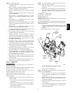
See Fig. 54--57 for thermostat connections. When installed with
a heat pump, the furnace control automatically changes the timing
sequence to avoid long blower off times during demand defrost
cycles. Whenever W/W1 is energized along with Y1 or Y/Y2, the
furnace control CPU will transition to or bring on the blower
motor BLWM at cooling airflow, low--heat airflow, or the
midrange airflow, whichever is lowest. The blower motor BLWM
will remain on until the main burners ignite then shut OFF and
remain OFF for 25 seconds before coming back on at heating
airflow. When the W/W1 input signal disappears, the furnace
control begins a normal inducer post-- purge period while
changing the blower airflow. If Y/Y2 input is still ener gized the
furnace control CPU will transition the blower motor BLWM
airflow to cooling airflow. If Y/Y2 input signal disappears and
the Y1 input is still energized the furnace control CPU will
transition the blower motor BLWM to low--cooling airflow. If
both the Y1 and Y/Y2 signals disappear at the same time, the
blower motor BLWM will remain on at low--heat airflow for the
selected blower--OFF delay period. At the end of the
blower--OFF delay, the blower motor BLWM will shut OFF
unless G is still energized, in which case the blower motor
BLWM will operate at continuous blower airflow.
Component T
est
The furnace features a component test system to help diagnose a
system problem in the case of a component failure. To initiate the
component test procedure, ensure that there are no thermostat
inputs to the control and all time delays have expired. Turn on
setup switch SW1--6. (See Fig. 33)
NOTE: The component test feature will not operate if the control
is receiving any thermostat signals or until all time delays have
expired.
The component test sequence is as follows:
1. The furnace control CPU turns the inducer motor IDM
ON at medium speed and keeps it ON through step 3.
2. After waiting 15 s econds the furnace control CPU turns
the hot surface igniter ON for 15 seconds, then OFF.
3. The furnace control CPU then turns the blower motor
BLWM ON at midrange airflow for 15 seconds, then OFF.
4. After shutting t he blower motor BLWM OFF the furnace
control CPU shuts the inducer motor IDM OFF.
NOTE: The EAC terminals are e ner gized when the blower i s
operating.
After the component test is completed , 1 or more status codes
(11, 25, 41, or 42) will flash. See Service Label on blower access
panel or Service/Status Code Instructions for explanation of
status codes.
NOTE: To repeat component test, turn setup switch SW1 --6 to
OFF and then back ON.
355CAV