


43
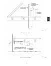
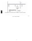
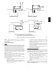
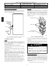
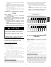
2. Locate heat tape between sides of condensate trap back.
(See Fig. 46.)
3. Use wire ties to secure heat tape in place. Wire ties can be
positioned in notches of condensate trap sides. (See Fig.
46.)
4. W rap field drain pipe with remaining heat tape,
approximately 1 wrap per ft.
5. When using field--supplied heat tape, follow heat tape
manufacturer’s instructions for all other installation
guidelines.
START--UP, ADJUSTMENT AND SAFETY
CHECK
Step 1 — General
1. Furnace must have a 115--v power supply properly
connected and grounded.
NOTE: Proper polarity must be maintained for 115--v wiring. If
polarity is incorrect, c ontrol status indicator light flashes r apidly
and furnace does not operate.
2. Thermostat wire connections at terminals R, W/W1, G,
and Y/Y2 must be made at 24--v terminal block on furnace
control.
3. Natural gas service pressure must not exceed 0.5 psig (14--
in. wc), but must be no less than 0.16 psig (4.5--in. wc).
4. Blower access panel must be in place to complete 115--v
electrical circuit to furnace.
UNIT MAY NOT OPERATE
Failure to follow this caution may result in intermittent unit
operation or performance satisfaction.
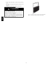
These furnaces are equipped with a manual reset limit
switch in burner box. This switch opens and shuts off
power to the gas valve if an overheat condition (flame
rollout) occurs in burner enclosure. Correct inadequate
combustion --air supply or improper venting condition
before resetting switch. DO NOT jumper this switch.
CAUTION
!
Before operating furnace, check flame rollout manual reset switch
for continuity. If necessary, press button to reset switch.
Step 2 — Select Setup Switch Positions
Air Conditioning (A/C) Setup Switches
The air conditioning setup switches are used to match furnace
airflow to cooling unit used.
To set the desired cooling airflow:
1. Remove main furnace door and blower access panel.
2. Locate A/C setup switches on furnace control. (See Fig.
33.)
3. Determine air conditioning tonnage used.
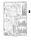
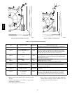
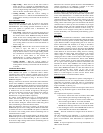
4. Use Fig. 47 or wiring schematic to determine proper setup
position of A/C switches. (See Fig. 48 and Fig. 49.)
NOTE: Excessive airflow caused by improper A/C switch setup
may cause condensate blowoff in cooling mode.
5. Replace main furnace door and blower access panel.
NOTE: EAC--1 terminal is energized whenever blower operates.
HUM terminal is only energized when blower is energized in
heating.
Continuous Fan (CF) S etup
Switches
The CF setup switches are used to select desired airflow when
thermostat is in continuous fan mode or to select low--cooling
airflow for two--speed cooling units. This setup feature allows
continuous fan airflow or low--cooling airflow to be adjusted. To
set desired continuous fan airflow or low--cooling airflow:
1. Remove main furnace door and blower access panel.
2. Locate CF setup switches on furnace control. (See Fig.
33.)
3. Determine desired continuous fan airflow or low--cooling
airflow.
4. Use Fig. 47 or wiring schematic to determine proper setup
position of CF switches. (See Fig. 48 and Fig. 49.)
5. Replace main furnace door and blower access panel.
525
2
700
2
700
875
1050
875
700 875
2
1050
1050
1
1225
1225
1225
1400
1400
1225
1750
1
1750
1
1225
1750
2100
DEF.
DEF.
DEF.
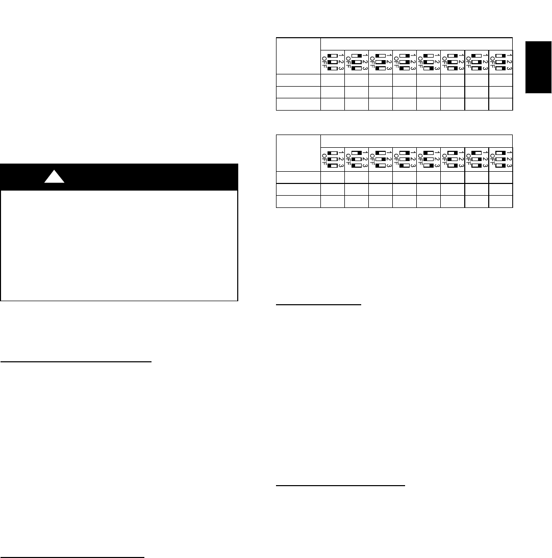
5T080, 100
120
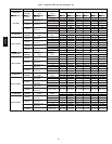
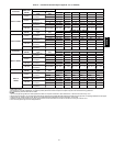
BASED ON 350 CFM/TON (SETUP SWITCH SW1-5 OFF)
SETUP SWITCH SW3 POSITIONS
MODEL
SIZE
600
2
800
2
800
1000
1200
1000
800 1000
2
1200
1200
1
1400
1400
1400
1600
1600
1400
2000
1
2000
1
1400
2000
2100
DEF.
DEF.
DEF.
060, 3.5T080
5T080, 100
120
BASED ON 400 CFM/TON (SETUP SWITCH SW1-5 ON)
1. DEFAULT A/C AIRFLOW WHEN A/C SWITCHES ARE IN OFF POSITION
2. DEFAULT CONT. FAN AIRFLOW WHEN CF SWITCHES ARE IN OFF POSITION
3. SWITCH POSITIONS ARE ALSO SHOWN ON FURNACE WIRING DIAGRAM
SETUP SWITCH SW3 POSITIONS
MODEL
SIZE
AIR CONDITIONING (A/C) OR CONTINUOUS-FAN (CF)
AIRFLOW SELECTION CHART
060, 3.5T080
A07424
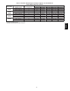
Fig. 47 -- A/C or CF Airflow Selection Chart Based on 350
and 400 CFM/Ton
Setup Switches
(SW1)
The furnace control has 8 setup switches that may be set to meet
the application requirements. To set these setup switches for the
appropriate requirement:
1. Remove main furnace door and blower access panel.
2. Locate setup switches on furnace control. (See Fig. 33.)
3. See Table 9 for setup switch description. (See Fig. 48 and
Fig. 49.)
4. Replace main furnace door and blower access panel.
NOTE: If a bypass humidifier is used, setup switch SW1--3
(Low Heat Rise Adjust) should be in ON position. This
compensates f or the increased temperature in return air resulting
from bypass.
NOTE: If modulating dampers are used, blower motor
automatically compensates for modulating dampers.
Additional Setup Switches
(SW4)
The furnace control has 3 additional setup switches labeled SW4.
(See Fig. 33.) Setup switch SW4--2 can be used to lock the
furnace into medium heat. When setup switch SW4 --2 is ON the
furnace will remain at medium heat until W/W1 is de--energized
to end a heating cycle or when both W/W1 and W2 are energized.
When both W/W1 and W2 are energized the furnace will run at
high heat. The other 2 setup switches are currently not used for
anything. When setup switch SW4--2 is ON it will over ride setup
switch SW1--2 if it is ON. To activate setup switch SW4--2:
1. Remove main furnace door and blower access panel.
355CAV