


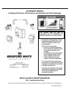
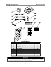
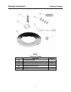
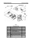
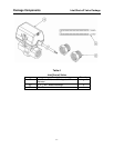
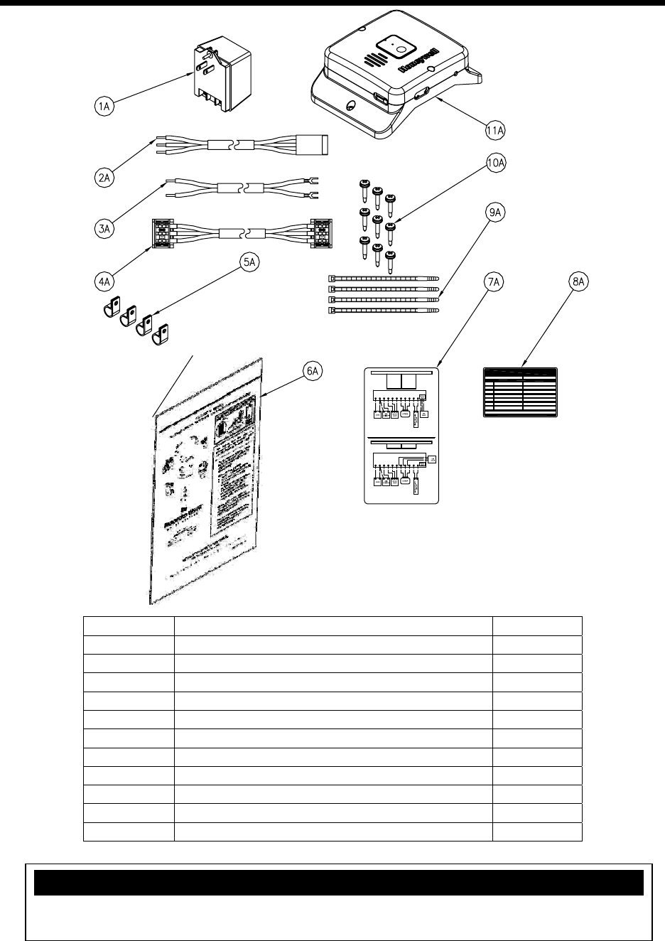
Package Components Accessory Module
-8-
Table 1
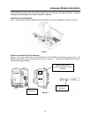
Accessory Module
Description Quantity
1A Plug-in Transformer 1
2A WV4460 Wire Harness 1
3A Transformer Wire Harness 1
4A WV8840 Wire Harness 1
5A Wire Holders 4
6A Installation & Operation Manual 1
7A Wiring Diagram Label 1
8A Diagnostic Label 1
9A Wire Ties 4
10A Screws 9
11A Accessory Module 1
NOTICE
The WV4460 wire harness must be used with gas controls with intermittent pilots. The WV8840
wire harness must be used with gas controls with standing pilots.
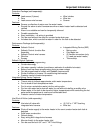
238-47880-00A
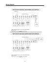
R1 C1 LK C2 NONC D/1R/2C/3 A1 A2
ACCESSORY MODULE
R1 C1 LK C2 NONC D/1R/2C/3 A1 A2
ACCESSORY MODULE
D
R
C
BK
W
R
BK BL BKBR R WBK BK Y
R
W
BK
BK
W
R
BK BL BKBR R WBK BK Y
R
BK
W
*WHEN CONNECTING LEAK SENSOR, REMOVE RESISTOR
BETWEEN C1 & LK.
**WHEN CONNECTING ANODE DEPLETION SENSOR, REMOVE RESISTOR
BETWEEN A1 & A2.
*WHEN CONNECTING LEAK SENSOR, REMOVE RESISTOR
BETWEEN C1 & LK.
**WHEN CONNECTING ANODE DEPLETION SENSOR, REMOVE RESISTOR
BETWEEN A1 & A2.
SEE INSTALLATION AND OPERATION MANUAL FOR MORE INFORMATION.
SEE INSTALLATION AND OPERATION MANUAL FOR MORE INFORMATION.
222-47463-01
222-47463-02
222-47464-01
222-47464-02
222-47465-01
222-47465-02
222-47466-01
222-47466-02
222-46402-01
222-46402-02
222-46990-01
222-46990-02
222-46991-01
222-46991-02
FOR USE WITH THE FOLLOWING GAS VALVES:
222-45613-01
222-45613-02
222-45614-01
222-45614-02
FOR USE WITH THE FOLLOWING GAS VALVES:
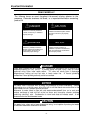
LED on continuously . Power on (no fault).
One flash and three second pau se. Leak alarm faul t. Water shut-off valve ope n.
Two flashes and three second p ause. Leak alarm faul t. Water shut-off valve closed.
Three flashes and three sec ond pause. Anode depletion alarm or not c onnected.
Four flashes and three sec ond pause. Leak se nsor malfunction.
Five flashes and three sec ond pause. Gas valve missing/no t connected.
RED LED strobe ( quick flashes). Hardware error.
AMBER
AMBER
AMBER
RED
RED
GREEN
COLOR PATTERN
ACCESSORY MODULE STATUS LED STATUS
See Installation and Operation Instructi on Manual for probable c auses
associated with each c ontrol status code.
ACCESSORY MODULE DIAGNOSTIC CODES
238-47879-00A