


Setback Control Installation
-35-
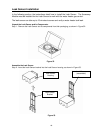
Connect the Setback Control Wire Harness and Accessory Module
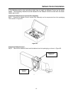
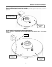
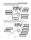
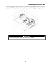
Step 17: Tighten the screw labeled “D/1,” as shown in Figure 44.
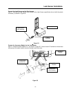
Assemble the Setback Control Wire Harness and Accessory Module – cont’d
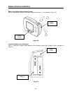
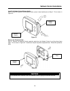
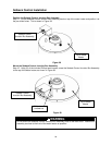
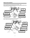
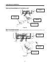
Step 18: If the water heater gas control has an intermittent pilot (WV4460 gas control), the connection,
“R/2,” is already being used. This same connection point is used to connect the Setback Control. Loosen
the screw “R/2.” This is shown in Figure 45.
Fi
g
ure 44
Figure 45
Accessory
Module
WV4460 Wire Harness
White Wire (if installed)
WV4460 Wire Harness
Black Wire (if installed)
WV4460 Wire Harness
Red Wire (if installed)
Setback Control Wire
Harness Red Wire
Philips head
screwdriver
Accessory
Module
WV4460 Wire Harness
White Wire (if installed)
WV4460 Wire Harness
Black Wire (if installed)
WV4460 Wire Harness
Red Wire (if installed)
Setback Control Wire
Harness Red Wire
Philips head
screwdriver
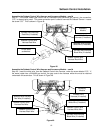
WV8840 Wire
Harness (if installed)
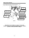
WV8840 Wire
Harness (if installed)