


D9412GV2/D7412GV2 | Operation and Installation Guide | Appendix A: System Wiring Diagrams, Issue A
66 Bosch Security Systems, Inc. | 5/05 | F01U003641B
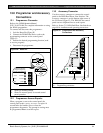
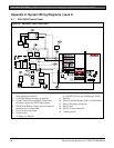
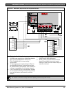
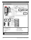
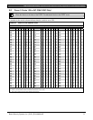
Figure 36: D9412GV2, SDI Devices
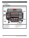
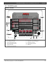
PERIPHERAL DEVICE CONNECTIONS
RED POWER +
YELLOW DATA BUS A
GREEN DATA BUS B
BLACK COMMON
ZONEX OUT 1
ZONEX IN 1
N.F.P.A.
Style 3.5
Signaling
Line
Circuits
32
31
30
29
28
27
ZONEX OUT 2
26
25
ZONEX IN 2
ZONEX POWER +
24
ZONEX COMMON
23
D8125
+
-
D8125
+
-
D8128D
D8128D
D8129
D8129
D9133TTL-E
D9131A
D9210B
D1260
D1257
D1256D1255
GRN
D5200/D5360
PROG CONN
Point 8
S3 Option
Closed = 1K
Ω
EOL
Normal Operation
Open =AB-12 UL
Bell Box 220 K
Ω
1 - Up to 8 supervised keypads
2 - Up to 8 D9210Bs
3 - Up to 3 supervised 9131As
4 - Power limited, supervised
5 - Power limited
6 - POPEX 1
7 - POPEX 2
8- Up to 119 D9127U/T POPITs or up to
63 D8127U/T POPITs
9 - Zonex 1: 15 D8128Ds
10 - Zonex 2: 15 D8128s
11 - Zonex 1: Up to 8 maximum
12 - Zonex 2: Up to 8 maximum
All external connections except Terminal 5 (battery position) are power limited.