


D9412GV2/D7412GV2 | Operation and Installation Guide | 4.0 Installation
.
Bosch Security Systems, Inc. | 5/05 | F01U003641B 19
4.7 Programming the Control Panel
If the control panel is not already programmed, review
the D9412GV2/D7412GV2 Program Entry Guide
(P/N: F01U003636). Ensure that all accessory modules
for desired features are available for installation. Place
the reset pin in the locked position to copy or send
information to and from the control panel.
Use the D5200 Programmer or the RPS to load a
custom program into the control panel.
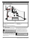
Move the reset pin to the normal position refer to
(Figure 4 on page 17). The control panel sends Reboot
and Battery Reports to the receiver if programmed for
reporting
4.8 Installing the Point Chart Label
The point chart label is required for fire
systems with verifications points.
A point chart label comes in the literature pack. Install
the point chart label for fire or combined fire-and-
burglary systems that use verification points.
Use the D9412GV2/D7412GV2 Program Record Sheet
(P/N: F01U003635) to gather the necessary information
for completing the point chart. Fill out the label and
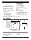
install it on the inside of the enclosure door (refer to
Figure 2 on page 15).
Avoid smearing the entries on the chart.
Use the peel-off backing to press the label
in place.
4.9 Testing the System
After installing and programming the control panel,
test the system completely. Test the control panel and
all devices for proper operation. Test after initially
programming the control panel and after subsequent
programming sessions.
Refer to the D9412GV2/D7412GV2/D7212GV2
Installation and Troubleshooting Quick Reference Guide
(P/N: F01U003638) for complete Service Walk Test
instructions.
Clear after Test: To clear the event memory and
report buffer, momentarily close the reset pin. Events
stored in the control panel’s event log are not cleared.