


D9412GV2/D7412GV2 | Operation and Installation Guide | 7.0 Telephone Connections
30 Bosch Security Systems, Inc. | 5/05 | F01U003641B
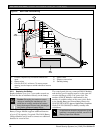
7.11.3 Installing the D928
Mounting
Mount the D928 on the lower right side of the
enclosure using the screws provided with the switcher.
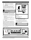
Wiring
The D928 has two flying leads. The green lead
monitors AC power. The black lead is the ground
reference for the AC Power LED.
1. Connect the green lead from the D928 to
Terminal 1.
2. Connect the black lead from the D928 to
Terminal 9.
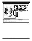
Telephone Connections
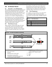
1. Plug one end of the ribbon cable provided into J4
on the control panel. Plug the other end of the
ribbon cable into the ACCESSORY connector on
the control panel.
2. Plug one end of the D162 phone cord provided
into the telco jack. Plug the other end of the phone
cord into the telco jack on the control panel. Refer
to
Error! Reference source not found.
for phone
cord lengths.
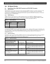
Table 9: Phone Cord Lengths
Phone Cord Length
D161 2.4 m (8 ft)
D162 61 cm (2 ft)
3. Plug one end of a D161 or D162 phone cord into
J1 on the control panel. Plug the other end of the
phone cord into the RJ31X or RJ138X for the
primary telephone line.
4. Plug one end of a D161 or D162 phone cord into
J2 on the control panel. Plug the other end of the
phone cord into the RJ31X or RJ138X for the
secondary telephone line. Refer to
Error!
Reference source not found.
for phone cord
lengths.
If you installed a D928 before November 19,
2001 on a D9412GV2 or D7412GV2,
disconnect AC power from the control panel
(battery must remain connected) and observe
the green LED.
If this LED glows dimly, contact Customer
Service at (800)289-0096 for a replacement
module at no charge.
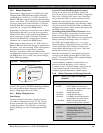
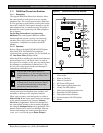
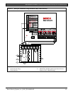
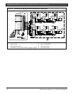
7.11.4 D928 Status LEDs
Four LEDs mounted on the front edge of the D928
Module show the status of AC power for the control
panel, the status of the two telephone lines, and
communication failure (Figure 11 on page 33). When
programmed and operating normally, only the green
AC power status LED is lit.
AC Power LED
The green AC Power Status LED lights when AC
power is applied to Terminals 1 and 2 on the control
panel.
Phone Line Fail LEDs
Two yellow Phone Line Status LEDs (one for the
primary telephone line, one for the secondary
telephone line) light if the voltage on the telephone line
falls to between 5.0 and 7.0 VDC, without the
corresponding current of 13 mA. The control panel
monitors the faulty telephone line for the programmed
interval before indicating a trouble condition. Refer to
Section 7.8 Telephone Line Monitor on page 28 for a
description of phone line monitor operation.
Communication Failure LED
The yellow Communication Failure LED lights when
the system is in communication failure. The LED turns
off when communication restores. Refer to Section 7.10
Communication Failure on page 28.